Molten metal transfer vessel and method of construction
Active Publication Date: 2016-08-09
MOLTEN METAL EQUIP INNOVIATIONS LLC
View PDF589 Cites 59 Cited by
Summary
Abstract
Description
Claims
Application Information
AI Technical Summary
This helps you quickly interpret patents by identifying the three key elements:
Problems solved by technology
Method used
Benefits of technology
Benefits of technology
[0026]A key advantage of the present system is that the amount of molten metal entering the launder, and the level in the launder, can remain constant regardless of the amount of or level of molten metal entering the transfer chamber with prior art systems, the metal level in the transfer chamber rises and falls and can affect the molten metal level in the launder. Alternatively, the molten metal can be removed from the vessel utilizing a tap-out plug, which is associated with the problems previously described.
[0032]Therefore, the problems with splashing and the formation of dross in the ladle or launder are greatly reduced or eliminated by utilizing this system.
[0033]In addition, preferably the pump used to transfer molten metal from the first chamber to the second chamber is a circulation pump (most preferred) or gas-release pump, preferably a variable speed pump. When utilizing such a pump there is an opening in the dividing wall beneath the level of molten metal in the first chamber during normal operation. The pump discharge communicates with, and may be received partially or totally in the opening. When the pump is operated it pumps molten metal through the opening and into the second chamber thereby raising the level in the second chamber until the level surpasses H2 and flows out of the second chamber. This embodiment of a system according to the invention eliminates the usage of a transfer pump and greatly reduces the problems associated therewith, such as dross formation, the formation of a solid plug of metal in the transfer pump riser or associated piping, and problems with tap-out holes.
[0035]Utilizing such a variable speed circulation pump or gas-release pump further reduces the chance of splashing and formation or dross, and reduces the chance of lags in which there is no molten metal being transferred or that could cause a device, such as a ladle, to be over filled. It leads to even and controlled transfer of molten metal from the vessel into another device or structure.
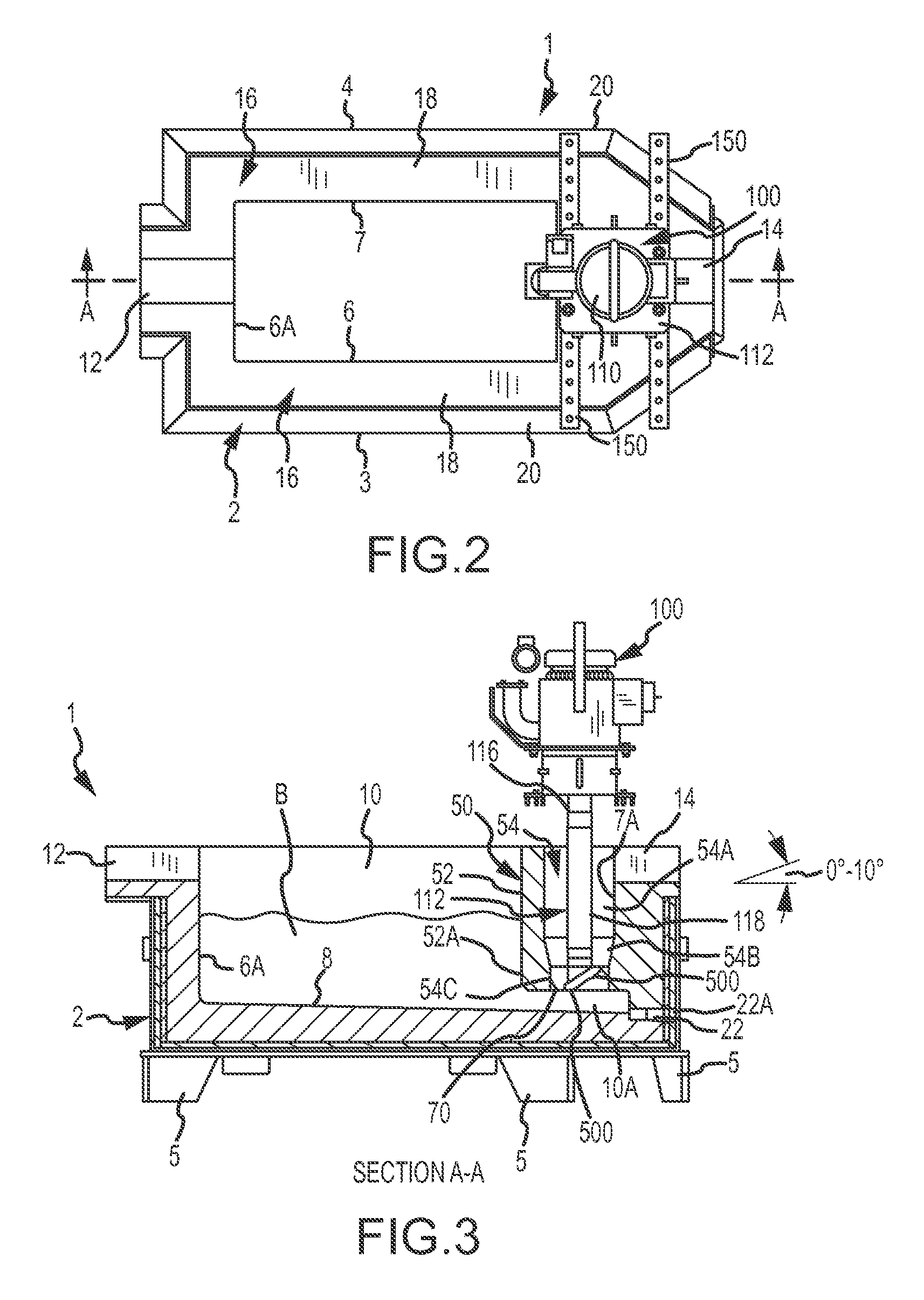
[0037]It has also been discovered that by making the launder either level (i.e., at a 0° incline) or inclined backwards towards the vessel so that molten metal in the launder drains back into the vessel, the dross or skin that forms on the surface of the molten metal in the launder is not pulled away with the molten metal entering downstream vessels. Thus, this dross is less likely to contaminate any finished product, which is a substantial benefit. Preferably, a launder according to the inventor is formed at a horizontal angle leaning back towards the vessel of 0° to 10°, or 0° to 5°, or 0° to 3°, or 1° to 3°, or at a slope of about ⅛″ for every 10′ of launder.
Problems solved by technology
Alternatively, the molten metal can be removed from the vessel utilizing a tap-out plug, which is associated with the problems previously described.
Method used
Image
Click on the blue label to locate the original text in one second.
Reading with bidirectional positioning of images and text.
Examples
Embodiment Construction
[0058]Turning now to the drawings, where the purpose is to describe a preferred embodiment of the invention and not to limit same, systems and devices according to the invention will be described.
[0059]The invention includes a transfer chamber used with a vessel for the purpose of transferring molten metal out of the vessel in a controlled fashion using a pump, rather than relying upon gravity. It also is more preferred than using a transfer pump having a standard riser tube (such as the transfer pumps disclosed in the Background section) because, among other things, the use of such pumps create turbulence that creates dross and the riser tube can become plugged with solid metal.
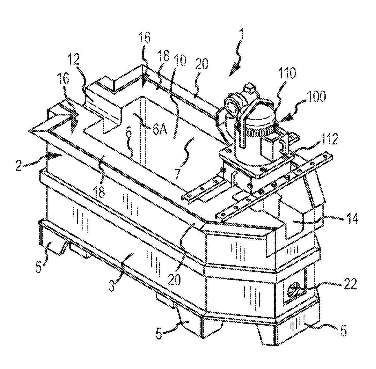
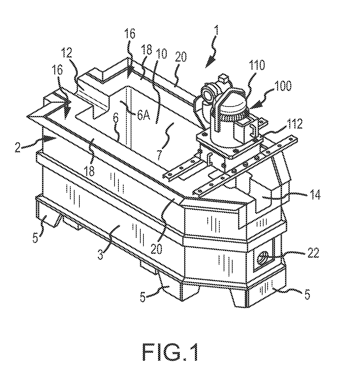
[0060]FIGS. 1-6 show one preferred embodiment of the invention. A system 1 comprises a vessel 2, a transfer chamber 50 and a pump 100. Vessel 2 can be any vessel that holds molten metal (depicted as molten metal bath B), and as shown in this embodiment is an intermediary holding vessel. Vessel 2 has a first ...
PUM
Property
Measurement
Unit
horizontal angle
aaaaa
aaaaa
horizontal angle
aaaaa
aaaaa
horizontal angle
aaaaa
aaaaa
Abstract
The invention relates to systems for transferring molten metal from one structure to another. Aspects of the invention include a transfer chamber constructed inside of or next to a vessel used to retain molten metal. The transfer chamber is in fluid communication with the vessel so molten metal from the vessel can enter the transfer chamber. A powered device, which may be inside of the transfer chamber, moves molten metal upward and out of the transfer chamber and preferably into a structure outside of the vessel, such as another vessel or a launder.
Description
CROSS-REFERENCE TO RELATED APPLICATIONS[0001]This application is a continuation-in-part of, and claims priority under 35 U.S.C. §§119 and 120 to, U.S. patent application Ser. No. 13 / 725,383, filed on Dec. 21, 2012, currently pending, by Paul V. Cooper, which is a divisional of, and claims priority to U.S. patent application Ser. No. 11 / 766,617 (Now U.S. Pat. No. 8,337,746), filed on Jun. 21, 2007, by Paul V. Cooper, the disclosure(s) of which that is not inconsistent with the present disclosure is incorporated herein by reference. This application incorporates by reference the portions of U.S. patent application Ser. No. 13 / 797,616 (Now U.S. Pat. No. 9,017,597), filed on Mar. 12, 2013, by Paul V. Cooper, that are not inconsistent with this disclosure.FIELD OF THE INVENTION[0002]The invention relates to a system for moving molten metal out of a vessel, and components used in such a system.BACKGROUND OF THE INVENTION[0003]As used herein, the term “molten metal” means any metal or comb...
Claims
Application Information
Patent Timeline
Application Date:The date an application was filed.
Publication Date:The date a patent or application was officially published.
First Publication Date:The earliest publication date of a patent with the same application number.
Issue Date:Publication date of the patent grant document.
PCT Entry Date:The Entry date of PCT National Phase.
Estimated Expiry Date:The statutory expiry date of a patent right according to the Patent Law, and it is the longest term of protection that the patent right can achieve without the termination of the patent right due to other reasons(Term extension factor has been taken into account ).
Invalid Date:Actual expiry date is based on effective date or publication date of legal transaction data of invalid patent.

