Transferring molten metal from one structure to another

a technology of molten metal and structure, applied in the direction of manufacturing converters, charge manipulation, furnaces, etc., can solve the problems of molten metal interfering more, safety hazards, use of most transfer pumps, etc., and achieve the effect of greatly reducing the risk of splashing and the formation of dross in the ladle or laundering

Active Publication Date: 2012-12-25
MOLTEN METAL EQUIP INNOVIATIONS LLC
View PDF494 Cites 71 Cited by
  • Summary
  • Abstract
  • Description
  • Claims
  • Application Information

AI Technical Summary

Benefits of technology

[0023]Therefore, the problems with splashing and the formation of dross in the ladle or launder are greatly reduced or eliminated by utilizing this system.
[0024]In addition, preferably the pump used to transfer molten metal from the first chamber to the second chamber is a circulation pump (most preferred) or gas-release pump, preferably a variable speed pump. When utilizing such a pump there is an opening in the dividing wall beneath the level of molten metal in the first chamber during normal operation. The pump discharge communicates with, and may be received partially or totally in the opening. When the pump is operated it pumps molten metal through the opening and into the second chamber thereby raising the level in the second chamber until the level surpasses H2 and flows out of the second chamber. This embodiment of a system according to the invention eliminates the usage of a transfer pump and greatly reduces the problems associated therewith, such as dross formation, the formation of a solid plug of metal in the transfer pump riser or associated piping, and problems with tap-out holes.
[0026]Utilizing such a variable speed circulation pump or gas-release pump further reduces the chance of splashing and formation or dross, and reduces the chance of lags in which there is no molten metal being transferred or that could cause a device, such as a ladle, to be over filled. It leads to even and controlled transfer of molten metal from the vessel into another device or structure.

Problems solved by technology

There are problems with each of these known methods.
This turbulence causes the molten metal to interact more with the air than would a smooth flow of molten metal pouring into the ladle.
The interaction with the air leads to the formation of dross within the ladle and splashing also creates a safety hazard because persons working near the ladle could be hit with molten metal.
Further, there are problems inherent with the use of most transfer pumps.
The blockage blocks the flow of molten metal through the pump and essentially causes a failure of the system.
This causes hours of expensive downtime.
The molten metal in the piping can also solidify causing failure of the system and downtime associated with replacing the piping.
Use of a tap-out hole at the bottom of a furnace can lead to problems.
First, when the tap-out plug is removed molten metal can splash or splatter causing a safety problem.
This is particularly true if the level of molten metal in the furnace is relatively high which leads to a relatively high pressure pushing molten metal out of the tap-out hole.
There is also a safety problem when the tap-out plug is reinserted into the tap-out hole because molten metal can splatter or splash onto personnel during this process.
Further, after the tap-out hole is plugged, it can still leak.
The leak may ultimately cause a fire, lead to physical harm of a person and / or the loss of a large amount of molten metal from the furnace that must then be cleaned up, or the leak and subsequent solidifying of the molten metal may lead to loss of the entire furnace.
Another problem with tap-out holes is that the molten metal at the bottom of the furnace can harden if not properly circulated thereby blocking the tap-out hole or the tap-out hole can be blocked by a piece of dross in the molten metal.
This system suffers from the problems previously described when using transfer pumps.

Method used


Image

  • Transferring molten metal from one structure to another
  • Transferring molten metal from one structure to another
  • Transferring molten metal from one structure to another

Examples


Embodiment Construction

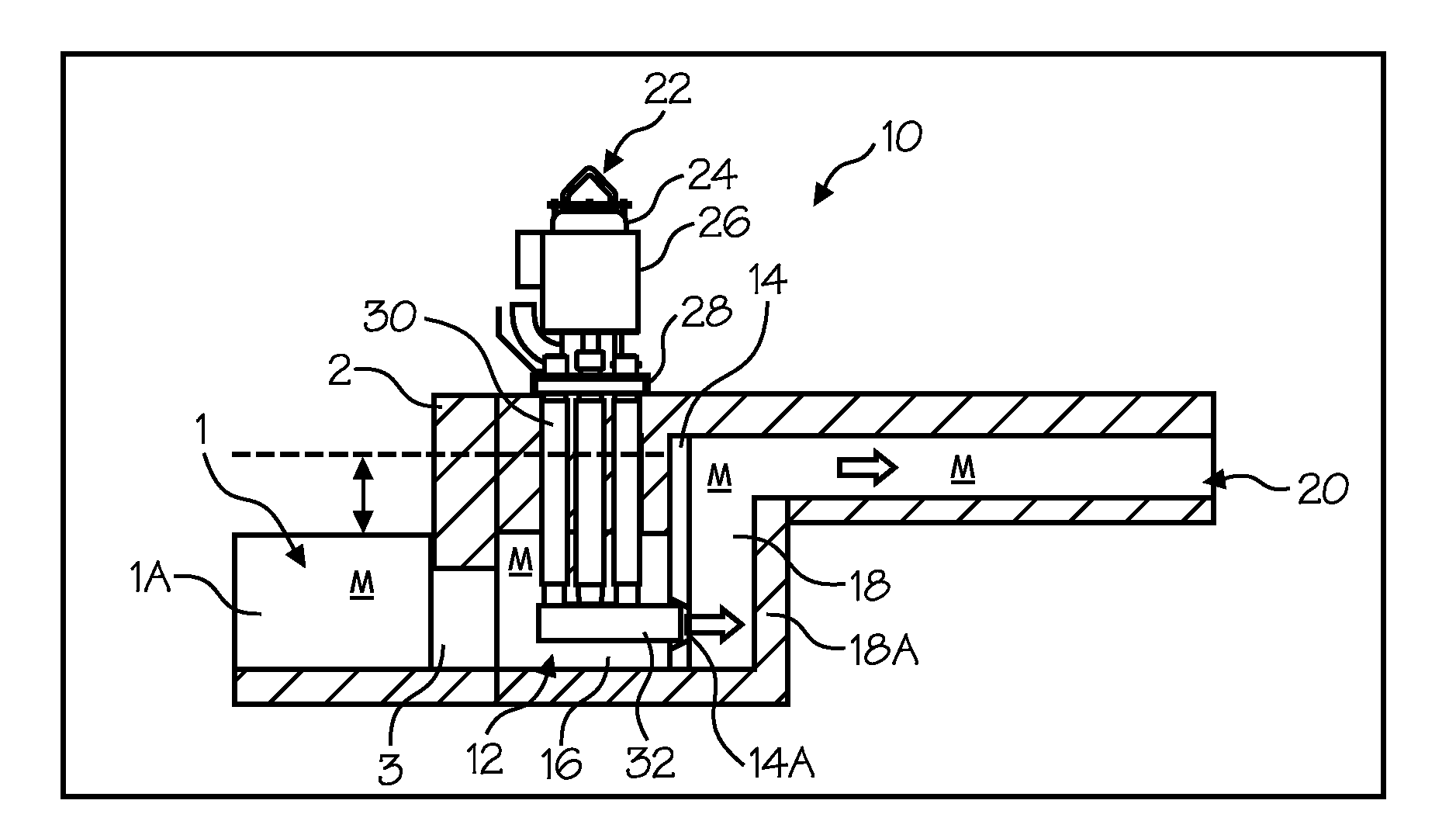
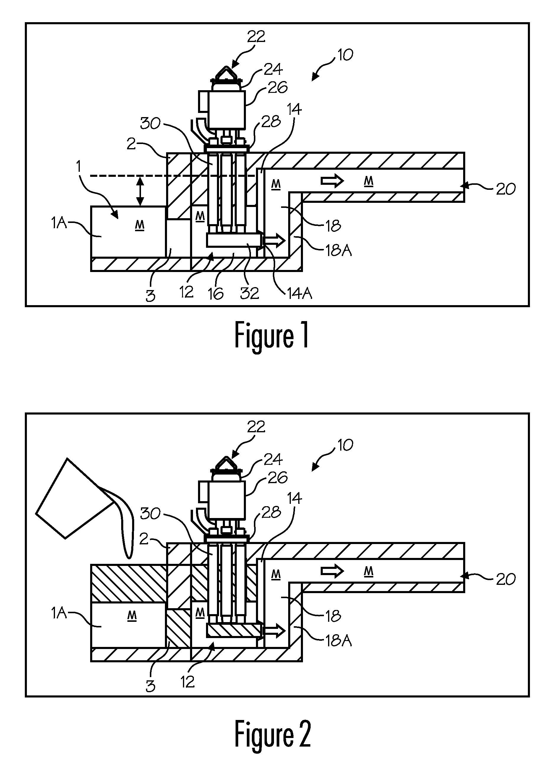
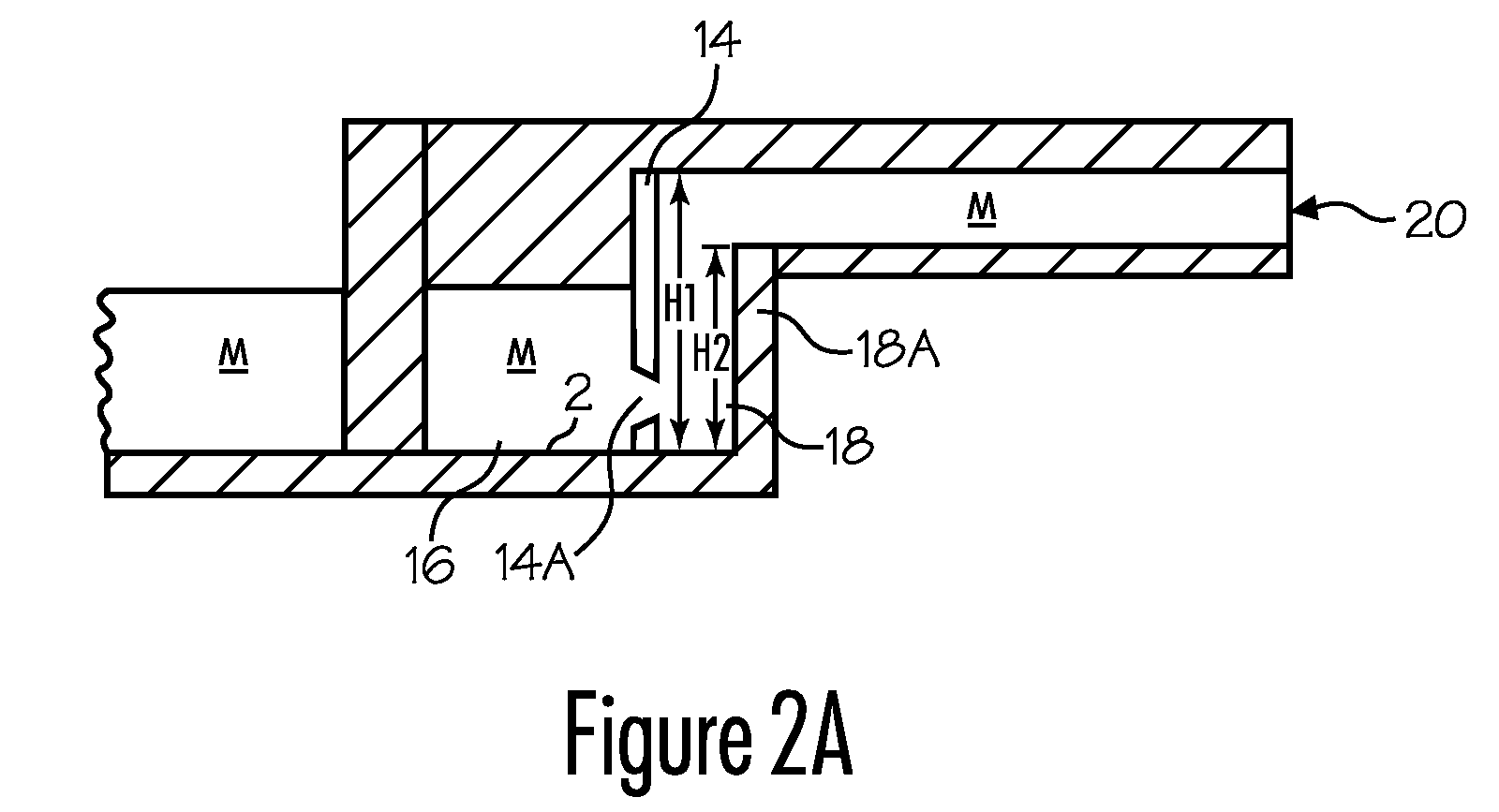
[0044]Turning now to the Figures, where the purpose is to describe preferred embodiments of the invention and not to limit same, FIGS. 1-3A show a system 10 for transferring molten metal M into a ladle or a launder 20. System 10 includes a furnace 1 that can retain molten metal M, which includes a holding furnace 1A, a vessel 12, a launder 20, and a pump 22. However, system 10 need only have a vessel 12, a dividing wall 14 to separate vessel 12 into at least a first chamber 16 and a second chamber 18, and a device or structure, which may be pump 22, for generating a stream of molten metal from first chamber 16 into second chamber 18.

[0045]Using heating elements (not shown in the figures), furnace 1 is raised to a temperature sufficient to maintain the metal therein (usually aluminum or zinc) in a molten state. The level of molten metal M in holding furnace 1A and in at least part of vessel 12 changes as metal is added or removed to furnace 1A, as can be seen in FIG. 2.

[0046]For expl...


PUM

PropertyMeasurementUnit
areaaaaaaaaaaa
lengthaaaaaaaaaa
lengthaaaaaaaaaa

Abstract

A system for transferring molten metal from a vessel and into one or more of a ladle, ingot mold, launder, feed die cast machine or other structure is disclosed. The system includes at least a vessel for containing molten metal, an overflow (or dividing) wall, and a device or structure, such as a molten metal pump, for generating a stream of molten metal. The dividing wall divides the vessel into a first chamber and a second chamber, wherein part of the second chamber has a height H2. The device for generating a stream of molten metal, which is preferably a molten metal pump, is preferably positioned in the first chamber. When the device operates, it generates a stream of molten metal from the first chamber and into the second chamber. When the level of molten metal in the second chamber exceeds H2, molten metal flows out of the vessel and into another structure, such as into one or more ladles and / or one or more launders.

Description

FIELD OF THE INVENTION[0001]The invention comprises a system and method for moving molten metal out of a vessel, such as a reverbatory furnace, and reducing or eliminating the safety and performance problems associated with many known methods.BACKGROUND OF THE INVENTION[0002]As used herein, the term “molten metal” means any metal or combination of metals in liquid form, such as aluminum, copper, iron, zinc and alloys thereof. The term “gas” means any gas or combination of gases, including argon, nitrogen, chlorine, fluorine, Freon, and helium, which may be released into molten metal.[0003]A reverbatory furnace is used to melt metal and retain the molten metal while the metal is in a molten state. The molten metal in the furnace is sometimes called the molten metal bath. Reverbatory furnaces usually include a chamber for retaining a molten metal pump and that chamber is sometimes referred to as the pump well.[0004]Known pumps for pumping molten metal (also called “molten-metal pumps”...

Claims


Application Information

Patent Timeline
Patent Type & Authority Patents(United States)
IPC IPC(8): B22D37/00C21C5/04F27D27/00
CPCC22B21/0084C22B21/064F27D3/14B22D39/00B22D7/00B22D37/00F27D27/005
Inventor COOPER, PAUL V.
Owner MOLTEN METAL EQUIP INNOVIATIONS LLC
Why Eureka
Try Eureka