Printer

a printing machine and printing plate technology, applied in the field of printing machines, can solve problems such as difficulty in appropriate printing of images, and achieve the effect of reducing the number of sensors

Inactive Publication Date: 2016-08-16
FUNAI ELECTRIC CO LTD
View PDF12 Cites 0 Cited by
  • Summary
  • Abstract
  • Description
  • Claims
  • Application Information

AI Technical Summary

Benefits of technology

[0007]One or more embodiments of the present invention provide a printer that can reduce the number of sensors for determining abnormalities in the feed condition of sheet-shaped recording media.
[0009]According to one or more embodiments of the present invention, the passage of the end edge of the recording medium during feeding in the forward direction and the passage of the end edge of the recording medium during feeding in the reverse direction can be detected by detecting the displacement of the displacement member. Further, abnormalities in the feed condition of a sheet-shaped recording medium can be determined by using a forward feed amount and a reverse feed amount based on the passage of the end edge of the recording medium during feeding in the forward direction and the passage of the end edge of the recording medium during feeding in the reverse direction that are detected in this manner. In other words, if the displacement of the displacement member can be detected, abnormalities in the feed condition can be determined The displacement of the displacement member can be detected without using a plurality of sensors. Thus, the number of sensors for determining abnormalities in the feed condition of a recording medium can be reduced.
[0012]According to one or more embodiments of the present invention, the passage of the end edge of the recording medium can be detected by detecting the rotation of the shaft due to the contact of the recording medium with at least one of the plurality of levers. Because the plurality of levers are disposed apart from each other in the width direction, the change in the reverse feed amount relative to the forward feed amount due to a slant in the recording medium relative to the direction of movement can be detected more accurately. In other words abnormalities in the feed condition of the recording medium can be determined more accurately.
[0014]According to one or more embodiments of the present invention, the third lever is disposed in a position corresponding to the end part of one side in the width direction of the recording medium of the second size, in a position between the first lever and the second lever. Thus, the change in the reverse feed amount relative to the forward feed amount due to the slant in the recording medium of the second size can be detected more accurately. In other words, in addition to the recording medium of the first size, abnormalities in the feed condition of the recording medium of the second size can be detected more accurately.
[0016]According to one or more embodiments of the present invention, in each lever, a slanted part is formed on the part colliding with the end edge of the recording medium fed in the forward direction over the discharge route disposed canted in the reverse direction relative to the route surface of the discharge route. Thus, the force placed on the recording medium when colliding can be suppressed, allowing for a more stable feed of the recording medium. According to one or more embodiments of the present invention, a printer that reverses a direction of movement of the recording medium, comprises a detection member that detects a slant in the recording medium relative to the direction of movement of the recording medium, based on at least two contact points between the detection member and the recording medium.
[0017]In one or more embodiments of the present invention, a printer can determine abnormalities in the feed condition of a sheet-shaped recording medium and suppress the increase of man-hours for building.

Problems solved by technology

When the paper cants diagonally, it becomes difficult to print the image appropriately.

Method used


Image

  • Printer
  • Printer
  • Printer

Examples


embodiments

(Embodiments)

[Physical Configuration of the Printer]

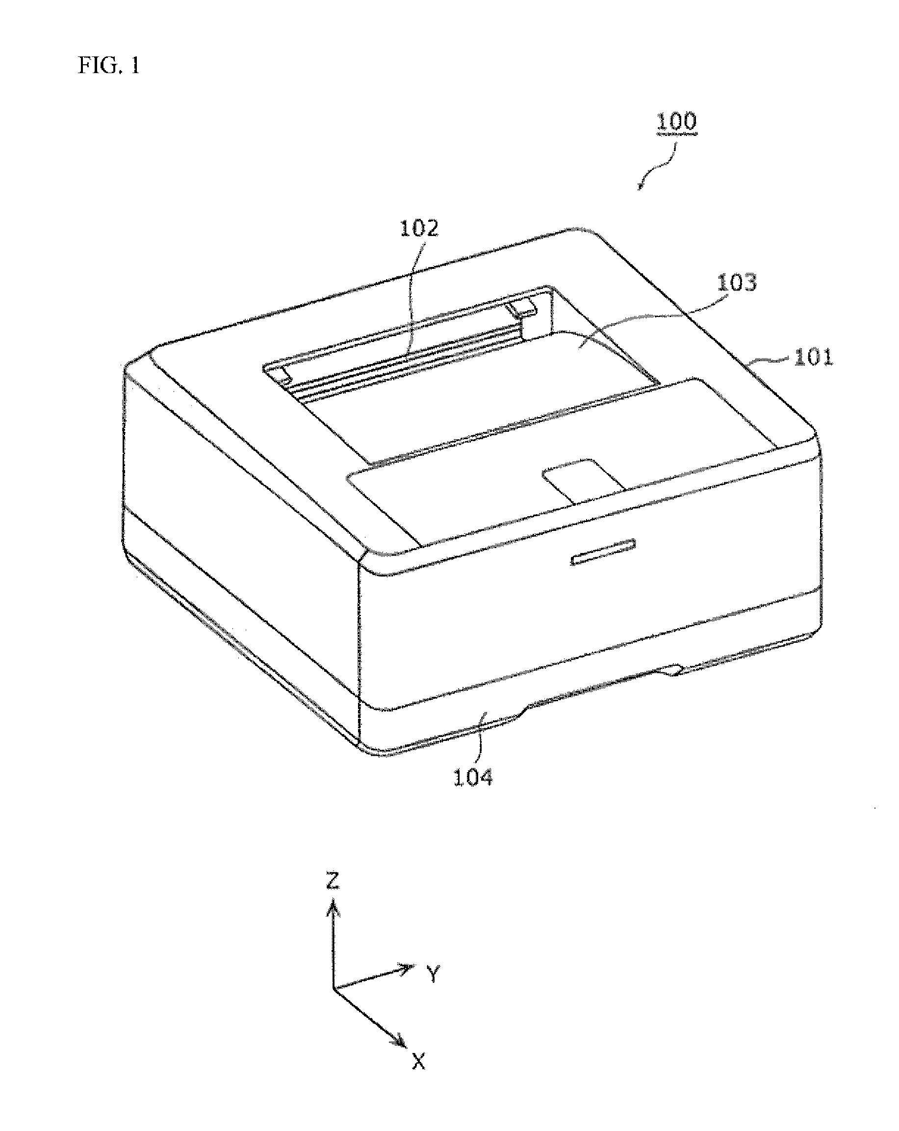
[0041]A physical configuration of a printer 100 in accordance with one or more embodiments of the present invention is described first. FIG. 1 is a perspective view showing an exterior view of the printer 100 according to one or more embodiments of the present invention.

[0042]The printer 100 performs double-sided printing by turning over the paper by feeding the paper in a reverse direction by reversing the direction of movement while the paper is fed in the forward direction along the discharge route for discharging the printed paper. In one or more embodiments of the present invention, the printer 100 is a laser printer.

[0043]As illustrated in FIG. 1, the printer 100 is equipped with a chassis 101, a discharge port 102 formed on the chassis 101, a catch tray 103, and a paper cassette 104.

[0044]The discharge port 102 is an aperture through which printed paper is discharged from the interior of the chassis 101. When double-sided pr...

modification 1

(Modification 1)

[0094]Next, a modification 1 of the embodiments is described. In one or more embodiments of the present modification, the number of levers contained in the displacement member is different than in the above embodiments. The displacement member is described below centered on points that differ from the above embodiments.

[0095]FIG. 11 is a perspective view of a displacement member 130A of the printer according to one or more embodiments of the modification 1. In FIG. 11, identical symbols are used for configuration elements identical to FIG. 3, and their description is omitted.

[0096]The displacement member 130A has two levers 132A. The two levers 132A contain a first lever 133 and a second lever 134. In other words, in the displacement member 130A of the present modification, the third lever 135 contained in the displacement member 130 of the above embodiments is missing. However, because the first lever 133 and the second lever 134 are provided, the displacement membe...

modification 2

(Modification 2)

[0098]A modification 2 of the embodiments is described next. In one or more embodiments of the present modification, the shape and number of the lever contained in the displacement member is different than the above embodiments. The displacement member is described below centered on points that differ from the above embodiments.

[0099]FIG. 12 is a perspective view of the displacement member 130B of the printer according to one or more embodiments of the modification 2. In FIG. 12, identical symbols are used for configuration elements identical to FIG. 3, and their description is omitted.

[0100]The displacement member 130B is equipped with a shaft 131 and a lever 132B. The lever 132B is provided longitudinally over the shaft 131, and is a plate-shaped member disposed so it protrudes facing the route surface 112a of the discharge route 112. Even when the lever 132B is shaped in this manner, the displacement member 130B can accurately detect the passage of the paper 200.

[...


PUM


Abstract

A printer that reverses a direction of movement of a medium, includes a detection member that detects a slant in the medium relative to the direction of movement of the medium, based on at least two contact points between the detection member and the medium.

Description

TECHNICAL FIELD[0001]The present invention relates to a printer that can perform double-sided printing.BACKGROUND ART[0002]In printers that can print on both sides of a printer paper, depending on the print unit, the paper is turned over and sent into the print unit again after printing on one side of the paper. In this manner, printing is performed by the print unit on the other side of the paper, and double-sided printing is realized.[0003]The turning over of the paper is, for example, performed in the following manner. First, a paper that has been printed on one side is fed in a forward direction along the discharge route. Then, while the paper is being fed in a forward direction along the discharge route, the direction of movement of the paper is reversed and the paper is fed in the reverse direction. The paper fed in the reverse direction is then sent into the turnover route for turning over the paper.[0004]When reversing the direction of movement for turning over the paper, th...

Claims


Application Information

Patent Timeline
Patent Type & Authority Patents(United States)
IPC IPC(8): G03G15/00G03G15/23B65H7/02B65H85/00
CPCG03G15/55G03G15/6567G03G15/234G03G15/6529G03G2215/00561G03G2215/00565G03G2215/00586
Inventor YAMADA, MASAHIRO
Owner FUNAI ELECTRIC CO LTD
Why Eureka
Try Eureka