
Towpoint speed control for a paving machine

a technology of paving machine and speed control, which is applied in the field of paving machines, can solve the problems of only controlling the thickness of the resulting paved mat, and 115 publications fail to address the problem of slow tow point adjustment speed

Active Publication Date: 2016-09-13
CATERPILLAR PAVING PROD INC
View PDF22 Cites 11 Cited by
  • Summary
  • Abstract
  • Description
  • Claims
  • Application Information

AI Technical Summary

Benefits of technology

This patent relates to a system and method for adjusting the maximum speed and the height of a tow point on an asphalt paving machine. The system includes a controller that receives signals from a user interface to change the tow point height and speed. The controller selects between a high set point speed and an operating speed for adjusting the tow point. The technical effects of this invention include improved control and efficiency of the asphalt paving machine by allowing for real-time adjustment of the tow point speed and height, which can lead to reduced paving time and costs.

Problems solved by technology

As a result, the thickness of the resulting paved mat could only be controlled by means of altering the screed angle of attack.
However, when creating an obstacle, such as a speed bump, or preparing the machine for transport, the fixed, slow speed can cause delays.
The '115 publication fails to address problems related to the slow tow point adjustment speed in manual operation mode.

Method used


Image

  • Towpoint speed control for a paving machine
  • Towpoint speed control for a paving machine
  • Towpoint speed control for a paving machine

Examples


Embodiment Construction

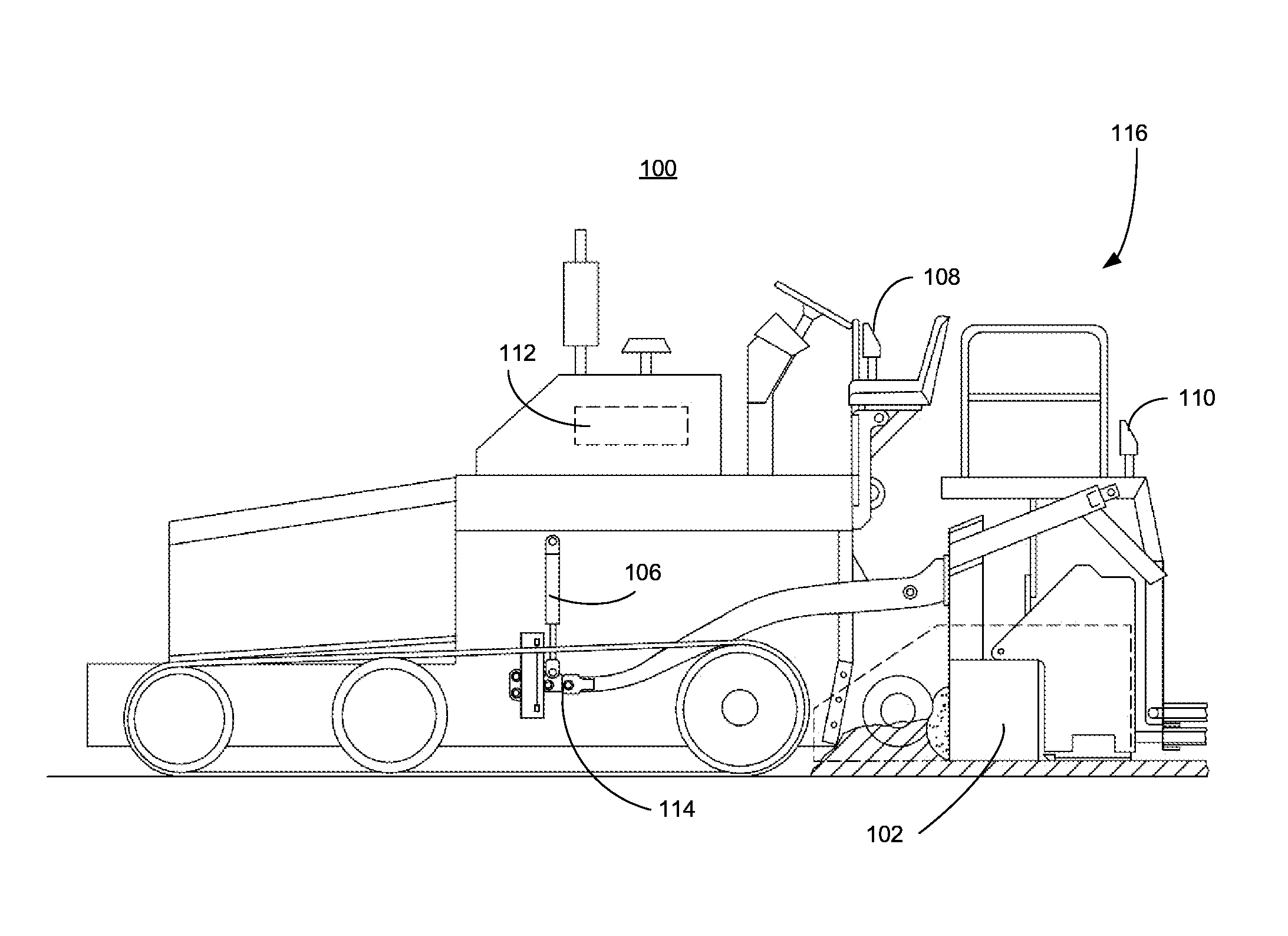
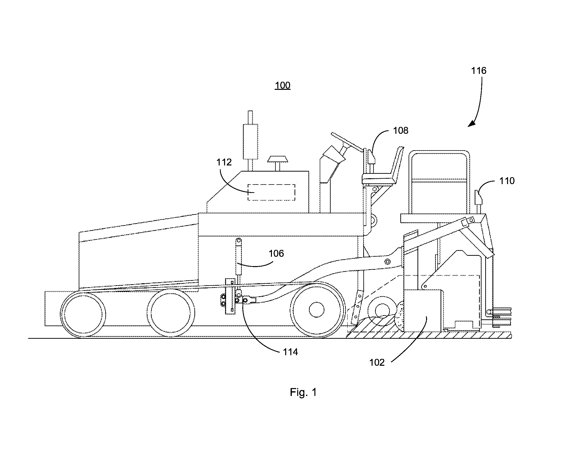
[0021]Referring to FIG. 1, an asphalt paving machine 100 includes a screed 102. The screed 102 forms the asphalt mat during a paving operation. As discussed above, the thickness and contour of the mat is controlled by a tow point adjuster 106 that raises and lowers a tow point 114 coupled to the screed 102 to change the screed height. Control of the mat thickness and contour may be made via a user interface 108 at an operator station or a user interface 110 on the screed 102. A controller 112 may receive inputs from one or both user interfaces 108, 110 and develop the proper outputs for operating the tow point adjuster 106. The user interfaces 108, 110 may also allow adjustment of paving machine speed, asphalt temperatures, and other screed settings as well as including condition indicators and warnings, such as oil pressure, fuel levels, etc. A tow point adjustment system 116 includes one or both of the user interfaces 108, 110, the controller 112, and the tow point adjuster 106.

[0...


PUM


Abstract

A controller receives inputs from a user interface that sets a speed for moving a tow point of an asphalt paving machine at a speed higher than a normal operating speed. The controller also receives signals from a user interface that moves the tow point in a selected direction at the set speed.

Description

TECHNICAL FIELD[0001]The present disclosure is generally directed to a paving machine and, more particularly, to selective control of a tow point for a screed of a paving machine.BACKGROUND[0002]“Floating screedasphalt finishing machines, or pavers, have provided an efficient and economical method of coating an old or new roadway with a compacted layer of asphalt aggregate for many years. Floating screed pavers are generally known to those skilled in the art, as reflected by the disclosure contained in U.K. Patent 1,054,151 to the Blaw-Knox Company. Such a paver typically comprises a self-propelled traction unit, or tractor, having a hopper at its front end for receiving paving material, such as asphalt aggregate, from a dump truck. A conveyor system on the machine transfers the paving material from the hopper rearwardly for distribution in front of a floating screed. Transversely arranged screw augers positioned at the rear end of the traction unit assist in moving the paving mat...

Claims


Application Information

Patent Timeline
Patent Type & Authority Patents(United States)
IPC IPC(8): E01C21/00E01C19/30E01C19/40E01C19/42E01C19/48
CPCE01C21/00E01C19/30E01C19/40E01C19/4866E01C19/42E01C19/48
Inventor FRELICH, TOBYHEDRINGTON, MATHEW
Owner CATERPILLAR PAVING PROD INC
Learn More