
Wrench quick release apparatus and wrench quick release handle

a quick release and wrench technology, applied in the direction of screws, threaded fasteners, instruments, etc., can solve the problems of inconvenient utilization, labor-saving and convenient fastening process, and complex time-consuming corresponding engagement and disengagement procedures, so as to achieve labor-saving and convenient manner, quick assembly or disassembly, and labor-saving and convenient

Active Publication Date: 2016-09-13
DTECH PRECISION INDS
View PDF16 Cites 6 Cited by
  • Summary
  • Abstract
  • Description
  • Claims
  • Application Information

AI Technical Summary

Benefits of technology

The present invention provides a wrench quick release apparatus and handle that allow for easy and quick assembly of objects with minimal effort. The apparatus includes a sleeve, positioning unit, wrench unit, and elasticity unit. The engaging section of the sleeve is connected to a first plate or object, and the positioning unit is driven by the user to engage or disengage the first and second plates or objects. The technical effects are that the apparatus allows for efficient and steady assembly of objects, and the handle is easy to use and secure.

Problems solved by technology

However, as previously described, the above structure that completes fastening by a screw thread requires an additional tool for applying a rotational force to the screw groove of the force receiving section of the screw for engagement or disengagement, which means that corresponding engagement and disengagement procedures are more complex and time-consuming.
Furthermore, although the prior art provides certain fastening approaches for assembling two objects, these conventional approaches involve fastening operations performed by manual forces that directly press fastening units.
Consequently, not only a fastening process of such conventional approach is rather laborious and unpractical, but also utilization inconvenience is resulted due to a lack of force applying section when disengaging the fastening units in reverse.

Method used


Image

  • Wrench quick release apparatus and wrench quick release handle
  • Wrench quick release apparatus and wrench quick release handle
  • Wrench quick release apparatus and wrench quick release handle

Examples


Embodiment Construction

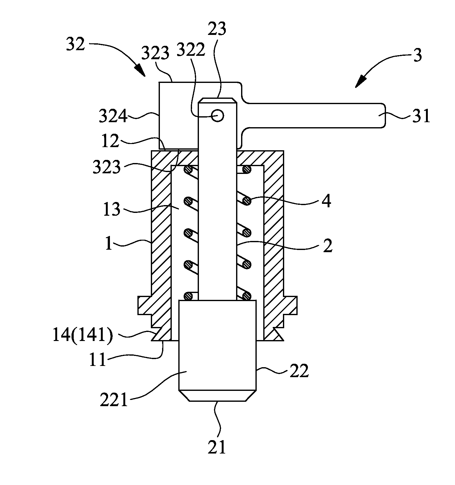
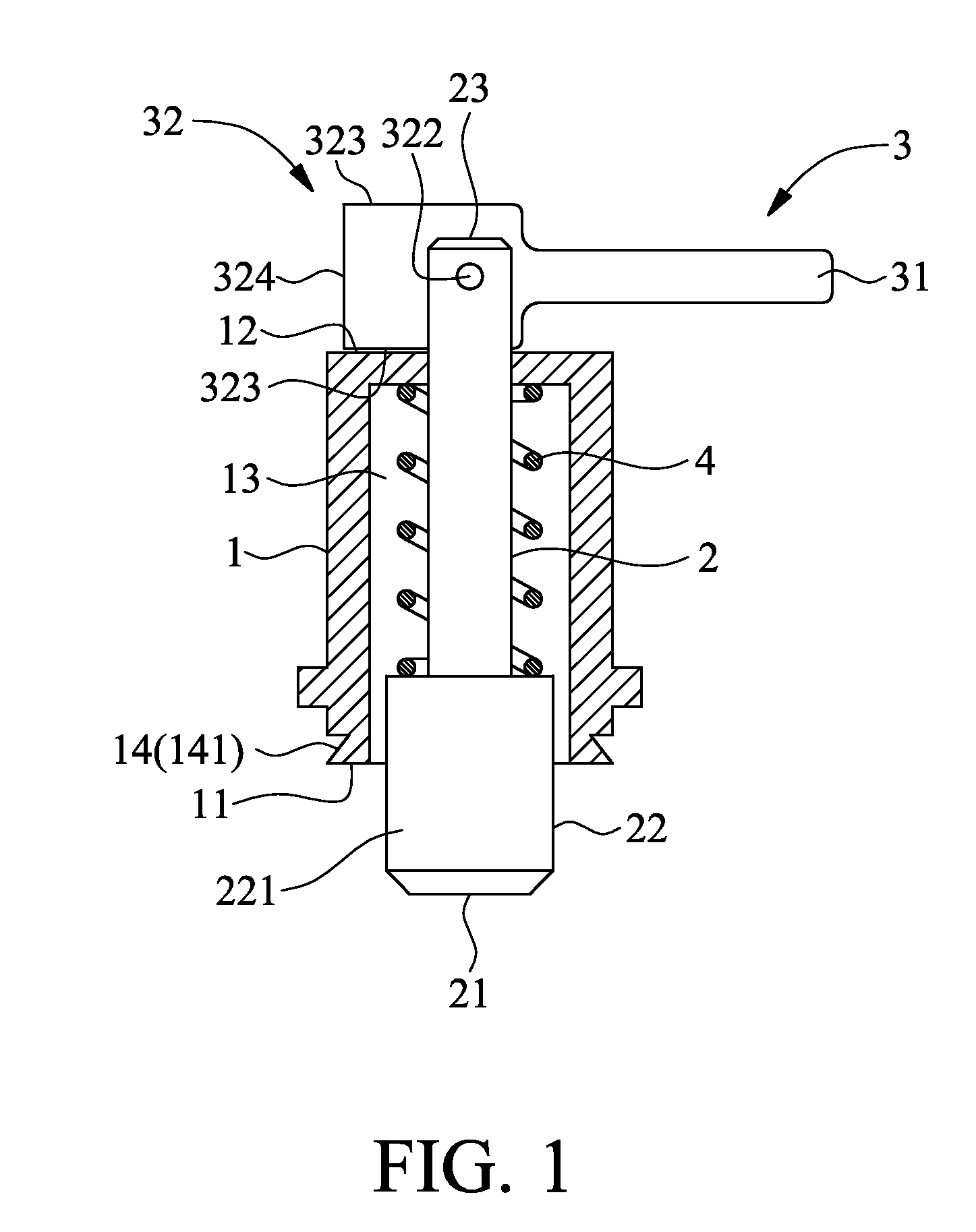
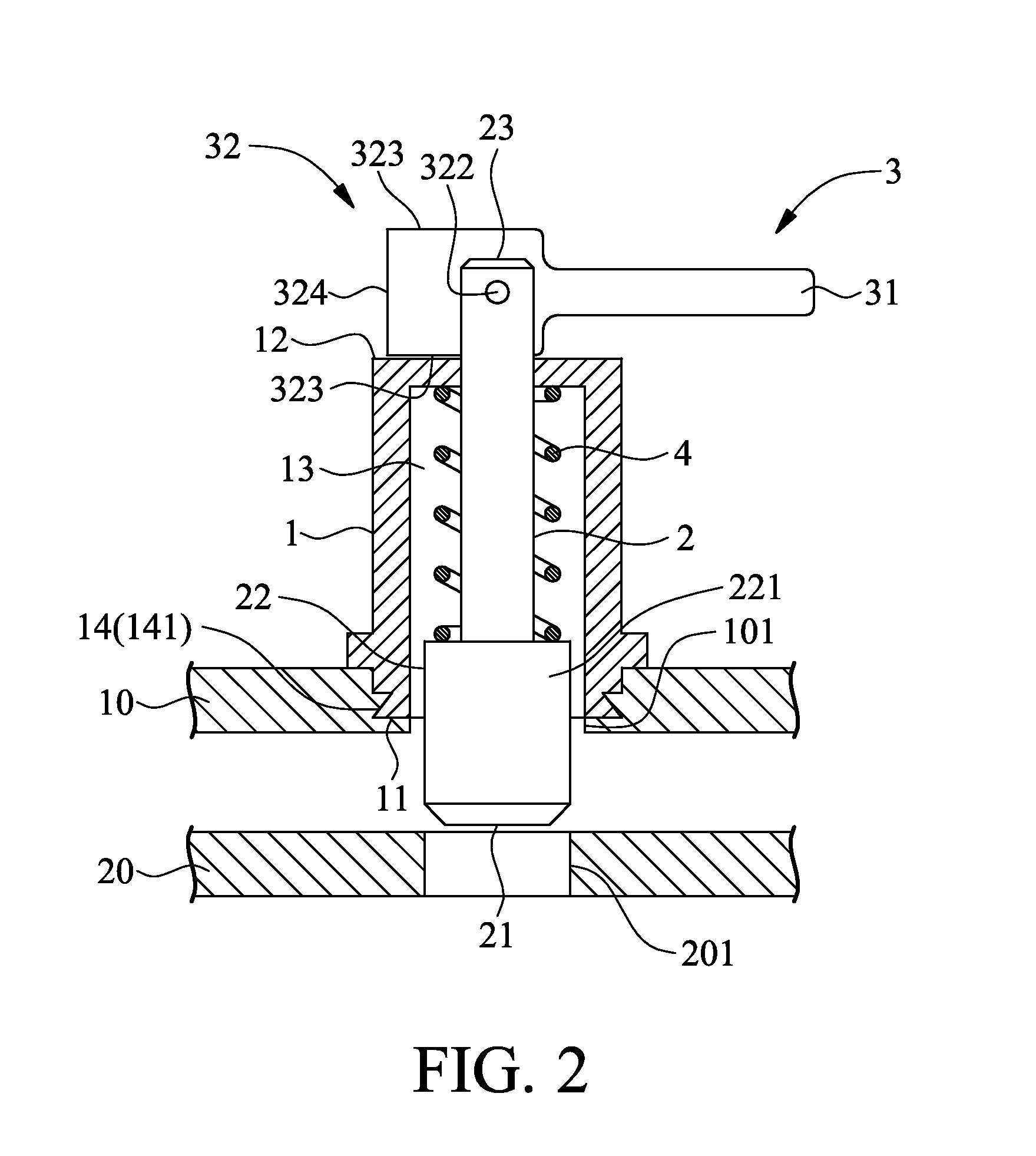
[0055]FIGS. 1, 2 and 3 show schematic diagrams of a wrench quick release apparatus according to an embodiment of the present invention. The wrench quick release apparatus is first engaged to a first plate 10 and then engaged to a second plate 20, so as to assemble the first plate 10 with the second plate 20. The wrench quick release apparatus according to a preferred embodiment of the present invention comprises a sleeve 1, a positioning unit 2, a wench unit 3, and an elasticity unit 4. The sleeve 1 comprises a first end 11, a second end 12 opposite to the first end 11, a channel 13 in communication with the first end 11 and the second end 12, and an engaging section 14 at the first end 11 for engaging to the first plate 10. The positioning unit 2, being a column body movably inserted in the channel 13 of the sleeve 1, comprises a positioning end 21 protruding to the first end 11 of the sleeve 1, a positioning section 22 provided at the positioning end 21 and for engaging the second...


PUM


Abstract

A wrench quick release apparatus includes a sleeve, a positioning unit, a wrench unit and an elasticity unit. The sleeve includes a channel and an engaging section for engaging to a first plate. The positioning unit inserts in the channel of the sleeve, and includes one end inserted through the first plate and an opposite end protrudes out from the channel of the sleeve. The wrench unit is pivotally connected to the positioning unit and protrudes out from one end of the sleeve. The elasticity unit includes one end pushed against the positioning unit and an opposite end pushed against the sleeve. Accordingly, the wrench quick release apparatus is first engaged to the first plate through the sleeve and then engaged to or disengaged from a second plate.

Description

CROSS-REFERENCE TO RELATED APPLICATION[0001]This application is a continuation-in-part patent application of U.S. application Ser. No. 13 / 344,127 filed on Jan. 5, 2012, the entire contents of which are hereby incorporated by reference for which priority is claimed under 35 U.S.C. §120.FIELD OF THE INVENTION[0002]The present invention relates to wrench quick release apparatuses and wrench quick release handles, and more particularly, to a wrench quick release apparatus for quickly assembling a first plate and a second plate and to a wrench quick release handle for quickly assembling or disassembling a first object and another object.BACKGROUND OF THE INVENTION[0003]Various approaches for assembling two plate-like objects (e.g., a motherboard and a housing) are available. A common approach is fastening through a screw thread structure which generally comprises a screw, a cap and a sleeve. The screw comprises an end of a larger diameter as a force receiving section provided with a scre...

Claims


Application Information

Patent Timeline
Patent Type & Authority Patents(United States)
IPC IPC(8): F16B5/00F16B5/06F16B17/00G06F1/18F16B19/10
CPCF16B5/00F16B5/0088F16B5/0642F16B17/006F16B19/109G06F1/184G06F1/186Y10T403/33Y10T403/595F16B2/185F16B5/0208
Inventor WANG, TING-JUI
Owner DTECH PRECISION INDS
Learn More