Proximity sensor for brake wear detection

a technology of wear detection and proximity sensor, which is applied in the direction of instruments, analogue processes for specific applications, electric/magnetic computing, etc., can solve the problems of inability to remotely perform the process of measuring steel rods, labor-intensive manual measurement process, and high cos

Active Publication Date: 2016-09-13
HONEYWELL INT INC
View PDF86 Cites 13 Cited by
  • Summary
  • Abstract
  • Description
  • Claims
  • Application Information

AI Technical Summary

Problems solved by technology

The process of measuring the steel rods manually is labor intensive, costly, time consuming and cannot be performed remotely.

Method used


Image

  • Proximity sensor for brake wear detection
  • Proximity sensor for brake wear detection
  • Proximity sensor for brake wear detection

Examples


first embodiment

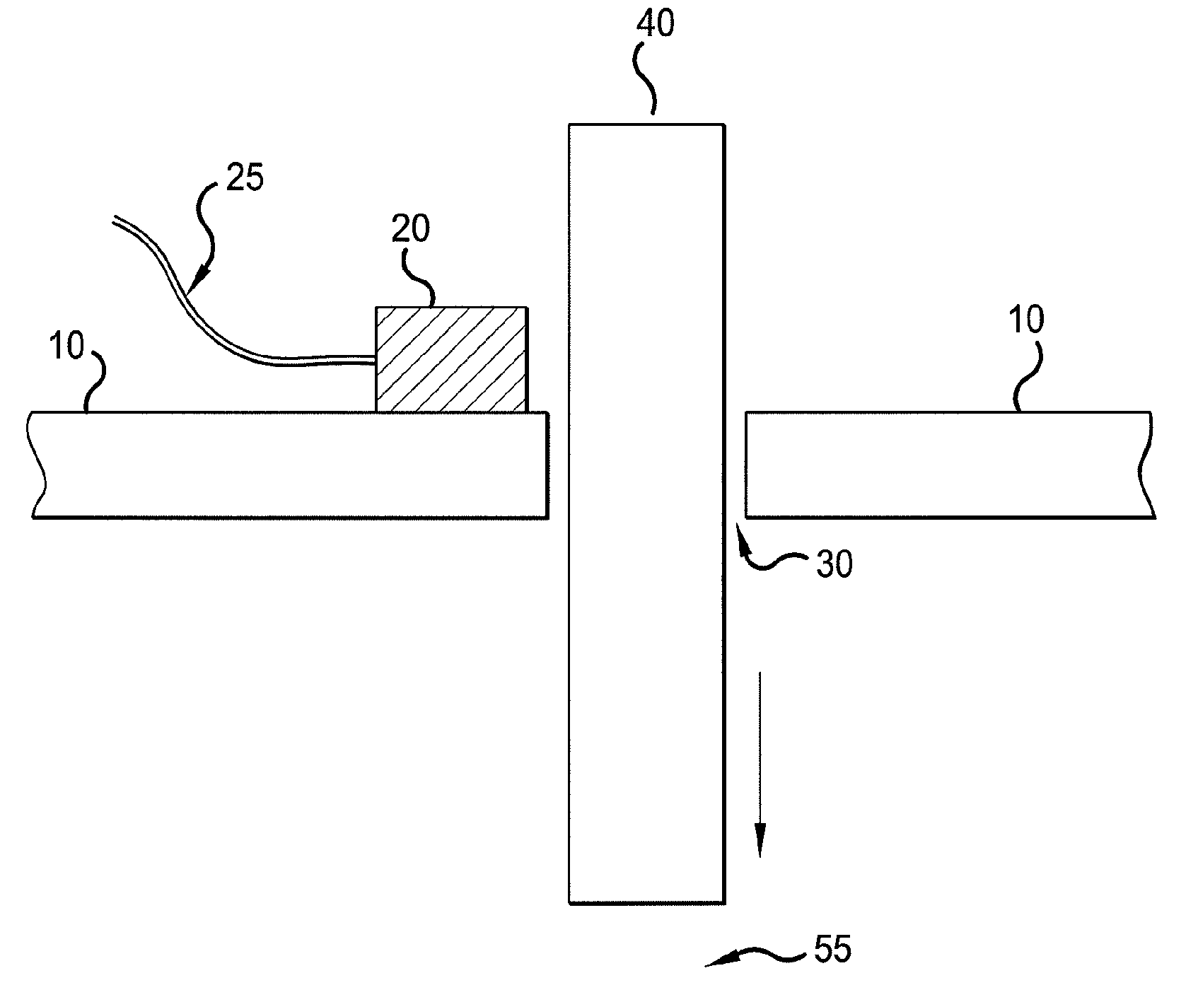
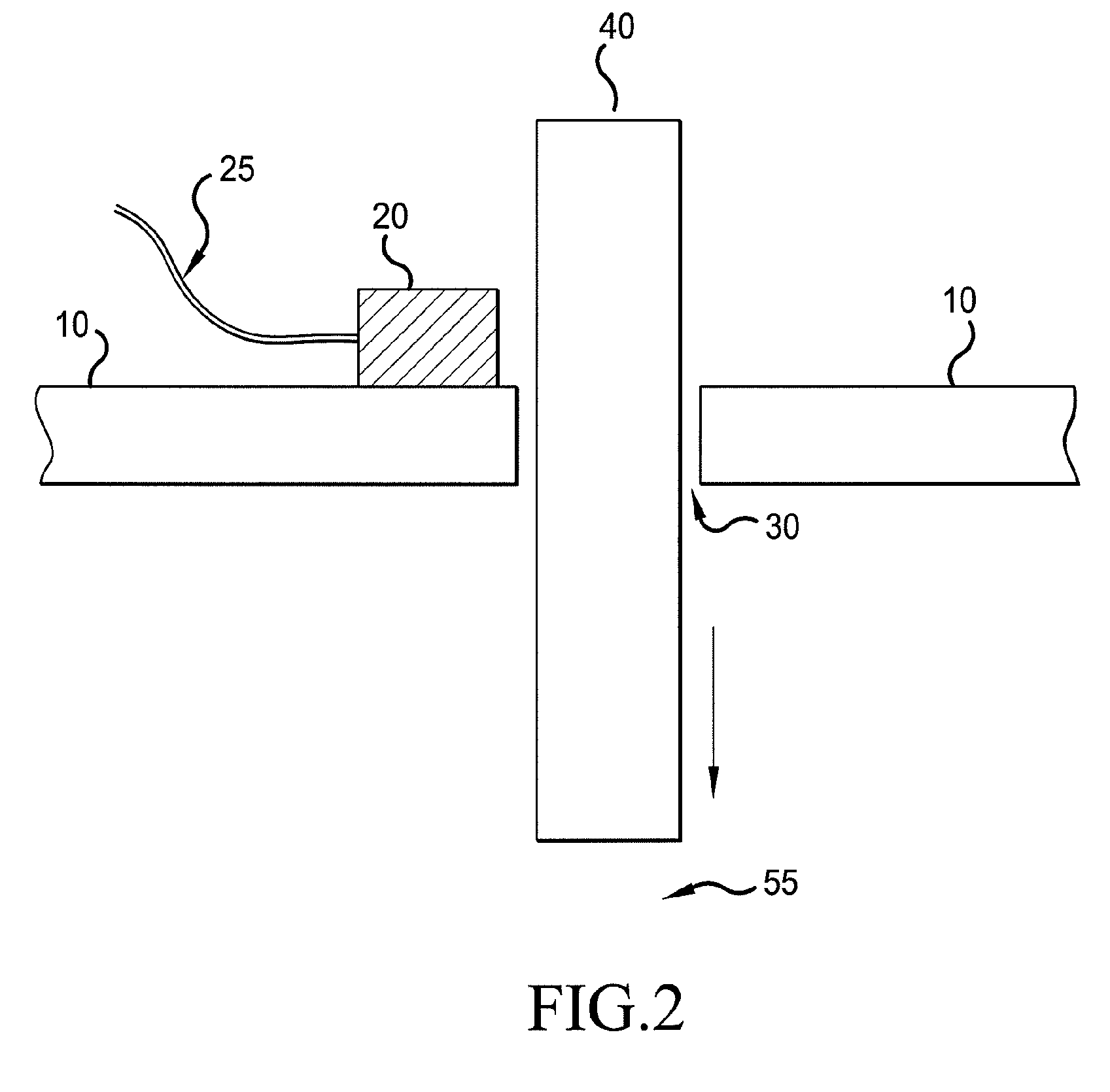
[0015]FIG. 2 shows a braking system which includes a sensor known as a reed switch 20 mounted on a bracket 10. The reed switch senses the location of a wear pin 40 or steel rod. The wear pin 40 passes through a hole 30 in the bracket 10 near brake disc stack 55. The wear pin 40 is used to measure the height of the brake disc stack 55. The location of the wear pin 40 corresponds with the height of the brake disc stack 55 and the wear of the brake disc stack 55. The wear pin 40 is magnetized so that a reed switch 20 can detect its presence. The reed switch 20 may be located on the outer surface of the bracket 10 while the brake disc stack 55 is located inside the inner surface of the bracket so that the reed switch 20 is oriented to measure the presence of the wear pin 40 protruding outside of the bracket 10. The reed switch 20 is securely fastened to the bracket 10 with the reed switch 20 located on the side of the bracket 10 opposite of the brake disc stack 55; however, the reed swi...

third embodiment

[0024]FIG. 4 shows the present invention. FIG. 4 includes a wear pin 50, a bracket 10 and a sensor 22. The sensor 22 is physically touching the wear pin 50 to measure its movement, such as a micro switch 22. The micro switch 22 includes as arm 23 that moves as the wear pin 50 moves. The amount the arm 23 moves corresponds to the change in height of the brake disc stack. As the brake disc stack 55 wears down, the micro switch 22 detects that the wear pin is moving in a direction that corresponds with the decrease in height of the brake disc stack 55. Upon moving to a predetermined position, the micro switch 22 sends a warning signal indicating that the height of the brake disc stack 55 has decreased a predetermined amount.

[0025]The difference between the third embodiment and the first and second embodiments is that the micro switch 22 of the third embodiment is physically touching the wear pin 50 while in the first and second embodiments, the reed switch does not touch the wear pin o...


PUM


Abstract

A proximity sensor 20, 21, 22 and method for detection of wear in a brake disc stack 55 on an aircraft including a wear pin 40, 43, 50 for moving in a first direction as the brake wears, and a switch 20, 21, 22 for measuring movement of the wear pin in the first direction. When the wear pin 40, 43, 50 moves in the first direction to a predetermined position, the switch 20, 21, 22 signals that the brake disc stack 55 has worn the predetermined amount.

Description

CROSS REFERENCE TO RELATED APPLICATIONS[0001]The present application claims the benefit of U.S. Provisional Patent Application No. 61 / 035,713 filed Mar. 11, 2008, the entire contents of which is hereby incorporated by reference.FIELD OF THE INVENTION[0002]This invention relates to an apparatus and method for detecting brake wear. The apparatus and method of the present invention is especially suitable for detecting brake wear in aircraft landing systems.BACKGROUND OF THE INVENTION[0003]Typically, to sense wear in aircraft brakes, a manual means is used to detect brake wear. In one known device, a steel rod passes through the bracket via a hole in the bracket. The amount of displacement that the steel rod moves, as it protrudes from the bracket, in relation to the steel rod's initial position corresponds with the amount of wear that has occurred on the brake disc stack. The brake disc stack is composed of a plurality of rotors and stators. The length of the steel rod protruding from ...

Claims


Application Information

Patent Timeline
Patent Type & Authority Patents(United States)
IPC IPC(8): F16D66/02
CPCF16D66/025
Inventor SCHAEFER, CRAIG
Owner HONEYWELL INT INC
Why Eureka
Try Eureka