Magnetron filter

a magnetron and filter technology, applied in the direction of microwave heating, transit-tube leading-in arrangements, etc., can solve the problems of limited effectiveness and inability to wind such high-gauge conductors into choke coils used in domestic cooker magnetrons, and achieve the effect of reducing stray emissions of magnetron

Active Publication Date: 2016-10-04
E2V TECH (UK) LTD
View PDF6 Cites 2 Cited by
  • Summary
  • Abstract
  • Description
  • Claims
  • Application Information

AI Technical Summary

Benefits of technology

[0008]In accordance with a first aspect of the present invention there is provided a low-pass filter for reducing stray emissions from a magnetron, wherein the filter is arranged for attachment to an exterior face of a wall of electrically conducting screening means for encasing the magnetron and for encasing an associated isolation transformer means electrically connected to terminals of the magnetron; and wherein an output connection of the filter passes directly through an interface between the electrically conducting screening means and the filter to connect electrically, directly or indirectly, with the isolation transformer.
[0013]Advantageously, inductors in neighbouring stages are orthogonal to each other to minimize coupling between the inductors.
[0015]Conveniently, the filter further comprises a first capacitor and a first resistor in series between the first line and the ground plane and a second capacitor and a second resistor connected in series between the second line and the ground plane to ensure a nominally matched impedance at frequencies of the stray radiation thereby minimizing gain of the filter at frequencies in the desired attenuation band but providing insignificant impedance to a waveform output from the heater supply inverter.
[0021]According to a second aspect of the invention, there is provided a method for reducing stray emissions from a magnetron, using a low-pass filter attached to an exterior face of a wall of electrically conducting screening means encasing the magnetron and encasing an associated isolation transformer means electrically connected to terminals of the magnetron; wherein an output connection of the filter passes directly through an interface between the electrically conducting screening means and the filter to connect electrically, directly or indirectly, with the isolation transformer.

Problems solved by technology

In particular, it would not be practical or economic to wind such high gauge conductors into a choke coil used for a domestic cooker magnetron.
A basic problem to be addressed is therefore that in a microwave source for industrial applications a magnetron requires a high voltage supply to be applied to the cathode, perhaps as much as −20 kV, together with a heater supply of typically 11 V at 110 A, derived from an isolation transformer (and rectifier if a DC heater is used) connected across heater and cathode terminals of the magnetron.
If a filter is fitted, its effectiveness may be limited by radiation picked up on its output.
Such a filter may provide no attenuation to the stray radiation because the filter itself acts as an antenna and picks up the stray radiation on its output even although the filter may have significant attenuation over the desired frequency band.

Method used


Image

  • Magnetron filter
  • Magnetron filter
  • Magnetron filter

Examples


Embodiment Construction

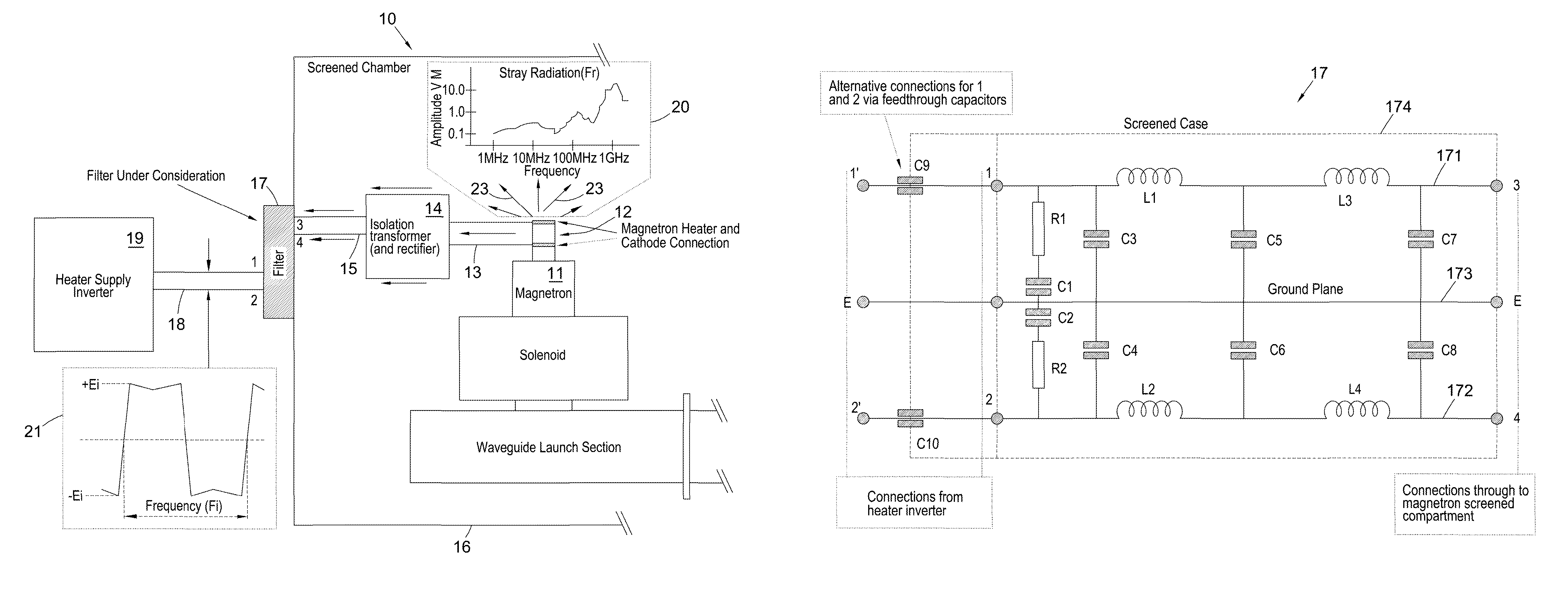
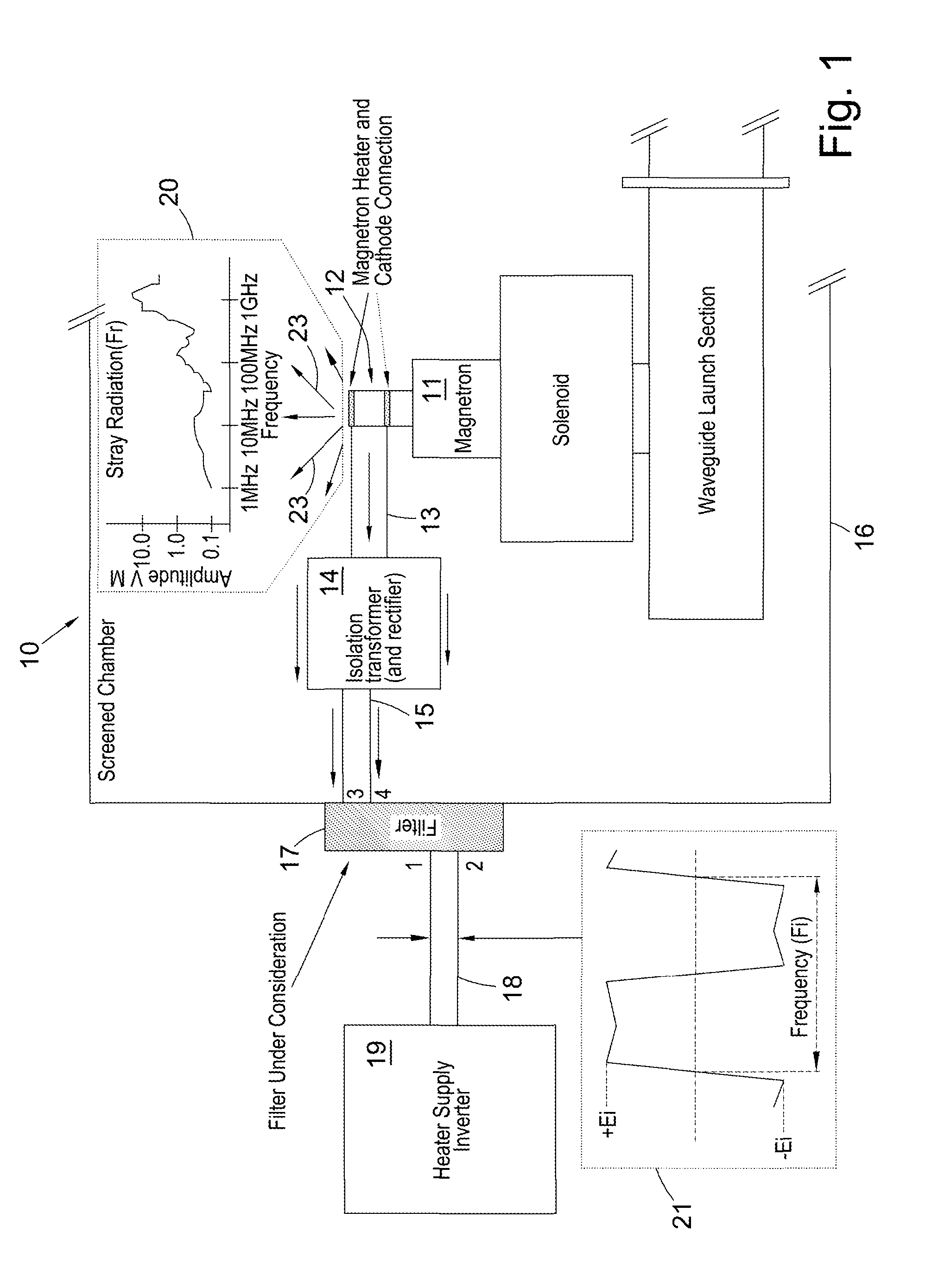
[0027]Referring to FIG. 1, a microwave radiation source 10, suitable for use with the invention, comprises a magnetron 11 with associated solenoid and waveguide launch section as shown, located in an electrically screened chamber 16. Also within the screened chamber 16 is an isolation transformer 14 connected to heater and cathode connections 12 of the magnetron 11 by output leads 13. Inputs of the isolation transformer are connected by input leads 15 to outputs 3, 4 of a filter 17 located externally on a wall of the screened chamber 16. Inputs 1, 2 of the filter 17 are connected by leads 18 to outputs of a heater supply inverter 19 external of the screened chamber 16. Locating the filter 17 outside the screened chamber 16 has the advantage of screening the filter components from the stray radiation 23 within the screened chamber 16.

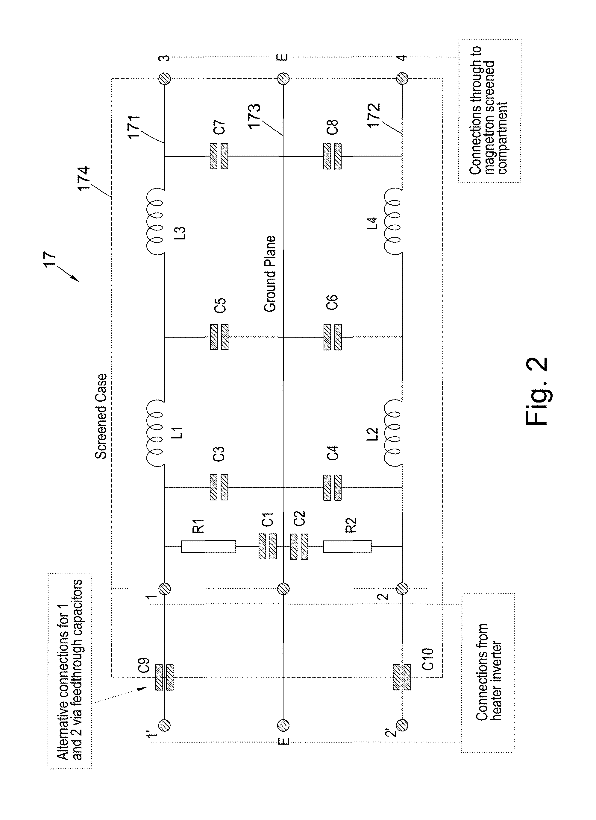
[0028]A circuit diagram of an embodiment of the filter 17 according to the invention is shown in FIG. 2, with a schematic layout of the filter shown in ...


PUM


Abstract

A low-filter is arranged for attachment to an exterior face of a wall of an electrically conducting screened chamber encasing the magnetron and an associated isolation transformer electrically connected to terminals of the magnetron. Output connections of the filter pass directly through an interface between the electrically conducting screened chamber and the filter to connect electrically, directly or indirectly, with the isolation transformer. There are therefore no electrical leads outside the screened chamber electrically connecting the filter to the isolation transformer.

Description

[0001]This invention relates to a filter for reducing stray emissions from a magnetron operating at frequencies in the vicinity of 900 MHz, and particularly in a range 890 to 930 MHz and to a method of filtering such stray emissions.BACKGROUND[0002]Magnetrons for known domestic ovens are provided with an L-C filter to prevent, as far as is possible, stray radiation generated by the magnetron from passing along the leads which supply power to the cathode heater. Such a filter, which is located at least partially within a screen chamber housing the magnetron terminals, is known from U.S. Pat. No. 4,900,985.[0003]A typical domestic cooker magnetron has a peak power of a few kilowatts, and an average power of around 1 kW and requires a heater current of around 10 A. However, for industrial RF processing applications, peak powers of several tens of kilowatts are needed, and a correspondingly larger heater supply is needed with typical currents of the order of 100 amps, so that much highe...

Claims


Application Information

Patent Timeline
Patent Type & Authority Patents(United States)
IPC IPC(8): H01J23/15H05B6/66
CPCH01J23/15H05B6/66
Inventor RICHARDSON, ROBERT X.OSBOURNE, KARL
Owner E2V TECH (UK) LTD
Why Eureka
Try Eureka