External cavity laser apparatus with orthogonal tuning of laser wavelength and cavity optical pathlength

a laser apparatus and laser wavelength technology, applied in the direction of optical elements, semiconductor lasers, instruments, etc., can solve the problems of inability to precisely tune the wavelength of operation within the interval of a mode hop, difficult implementation of this design, and transmission errors in modulated data streams, etc., to achieve minimal effect, minimize coupling, and minimize the effect of the passband of the tuning filter

Inactive Publication Date: 2005-05-31
INTEL CORP
View PDF83 Cites 20 Cited by
  • Summary
  • Abstract
  • Description
  • Claims
  • Application Information

AI Technical Summary

Benefits of technology

[0010]The invention provides an external cavity laser system and method wherein wavelength or channel selection is carried out independently from adjustment of external cavity optical path length. In general terms, the invention is an external cavity laser apparatus comprising a wavelength or channel selector tuner and an external cavity tuner, wherein the wavelength tuner is uncoupled or decoupled from the external cavity tuner, or wherein such coupling is minimized. In other words, the tuning mechanisms for wavelength selection and cavity optical path length are configured to operate independently or orthogonally with respect to each other such that tuning the wavelength passband of the tuning filter has minimal effect on the effective cavity length, and adjusting the effective cavity length has minimal effect on the passband of the tuning filter.

Problems solved by technology

One problem which can arise with such tunable lasers is “mode-hopping” wherein the laser changes frequency discontinuously to a different longitudinal mode.
When used as a telecommunication transmitter, these mode hops will cause transmission errors in the modulated data stream.
The modes themselves are not controlled, and thus the wavelength of operation cannot be precisely tuned within the interval of a mode hop.
This approach can potentially avoid the mode hopping problem and can tune to all wavelength but the constraint of synchronous adjustment makes the implementation of this design difficult.
This type of mode hop-free tuning, however, has proved to be non-optimal for stable tuning to narrowly spaced transmission bands, as is required for high bandwidth DWDM systems.
Mode hop-free tuning is often difficult to implement and in many cases involves a time-consuming location of a specific or “magic” pivot point to provide a specific rotation / translation relationship for tuning the grating and optical cavity length.
Although a mode hop free tuning architecture may be a good design choice for a test and measurement laser, it is not necessarily an optimal design choice for a tunable DWDM transmitter source.
In general, emission at any other wavelength cannot be sent into the system since this may cause crosstalk between the channel being tuned and other transmission channels.
In view of these design considerations, a mode hop free tuning approach does not confer the same advantages in DWDM source applications as it does in a test and measurement application.

Method used


Image

  • External cavity laser apparatus with orthogonal tuning of laser wavelength and cavity optical pathlength
  • External cavity laser apparatus with orthogonal tuning of laser wavelength and cavity optical pathlength
  • External cavity laser apparatus with orthogonal tuning of laser wavelength and cavity optical pathlength

Examples


Embodiment Construction

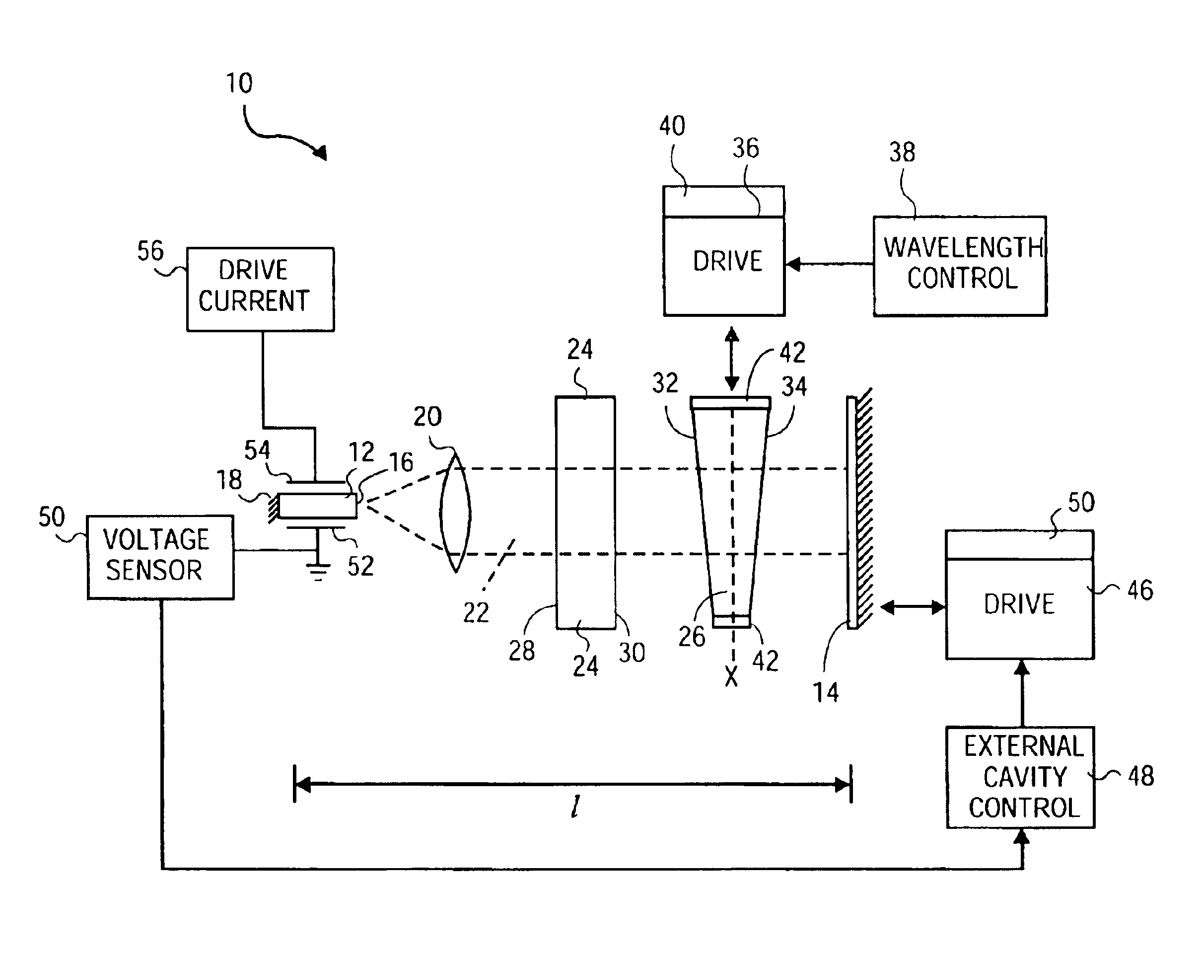
[0027]Referring more specifically to the drawings, for illustrative purposes the present invention is embodied in the apparatus and method shown in FIG. 1 through FIG. 6. It will be appreciated that the apparatus may vary as to configuration and as to details of the parts, and that the method may vary as to details and the order of events, without departing from the basic concepts as disclosed herein. The invention is disclosed primarily in terms of use with an external cavity laser. However, it will be readily apparent to those skilled in the art that the invention may be used with other types of lasers and optical systems. It also should be understood that the terminology used herein is for the purpose of describing particular embodiments only, and is not intended to be limiting.

[0028]A fundamental underlying physical principle of steady state laser operation is that the electric field of the optical wave inside the cavity reproduce itself after traversing a round trip in the cavi...


PUM

PropertyMeasurementUnit
temperatureaaaaaaaaaa
wavelengthaaaaaaaaaa

Abstract

An external cavity laser apparatus and method wherein wavelength or channel selection is carried independently from adjustment of external cavity optical path length. The apparatus comprises a wavelength or channel selector tuner and an external cavity tuner, wherein the wavelength tuner is uncoupled from the external cavity tuner. The tuning mechanisms for wavelength selection and cavity optical path length are configured to operate independently or orthogonally with respect to each other. The wavelength tuner may operate according to a first, channel selection signal, while the external cavity tuner operates according to a second, external cavity adjustment signal. The wavelength tuner and external cavity tuner may operate under the control of the same, or of separate controllers. The channel selection signal may be derived from a look-up table of adjustment parameter data accessed by a controller, and the external cavity adjustment signal may be derived from an error signal from a detector configured to measure external cavity loss.

Description

CROSS REFERENCEBACKGROUND OF THE INVENTION[0001]Fiber optic telecommunications are continually subject to demand for increased bandwidth. One way that bandwidth expansion has been accomplished is through dense wavelength division multiplexing (DWDM) wherein multiple separate data streams exist concurrently in a single optical fiber, with modulation of each data stream occurring on a different channel. Each data stream is modulated onto the output beam of a corresponding semiconductor transmitter laser operating at a specific channel wavelength, and the modulated outputs from the semiconductor lasers are combined onto a single fiber for transmission in their respective channels. The International Telecommunications Union (ITU) presently requires channel separations of approximately 0.4 nanometers, or about 50 GHz. This channel separation allows up to 128 channels to be carried by a single fiber within the bandwidth range of currently available fibers and fiber amplifiers. Improvement...

Claims


Application Information

Patent Timeline
Patent Type & Authority Patents(United States)
IPC IPC(8): H01S5/00H01S5/14H01S5/06H01S5/0687H01S5/022G02B26/06G02F1/03G02F1/13H01S3/106
CPCH01S5/141H01S3/105H01S3/1055H01S3/1062H01S5/0617H01S5/0687H01S5/0222H01S5/06
Inventor LI, HUACHAPMAN, WILLIAM B.DAIBER, ANDREWFARINAS, ALEJANDRO D.
Owner INTEL CORP
Why Eureka
Try Eureka