

Method and system for torque/force control of hydraulic actuators
a technology of hydraulic actuators and torque/force, applied in the direction of anti-hunting elements, instruments, electric digital data processing, etc., can solve the problems of complex treatment of situation, performance degradation, and difficult precise control of hydraulic actuators
- Summary
- Abstract
- Description
- Claims
- Application Information
AI Technical Summary
Benefits of technology
Problems solved by technology
Method used
Image

Examples
case a
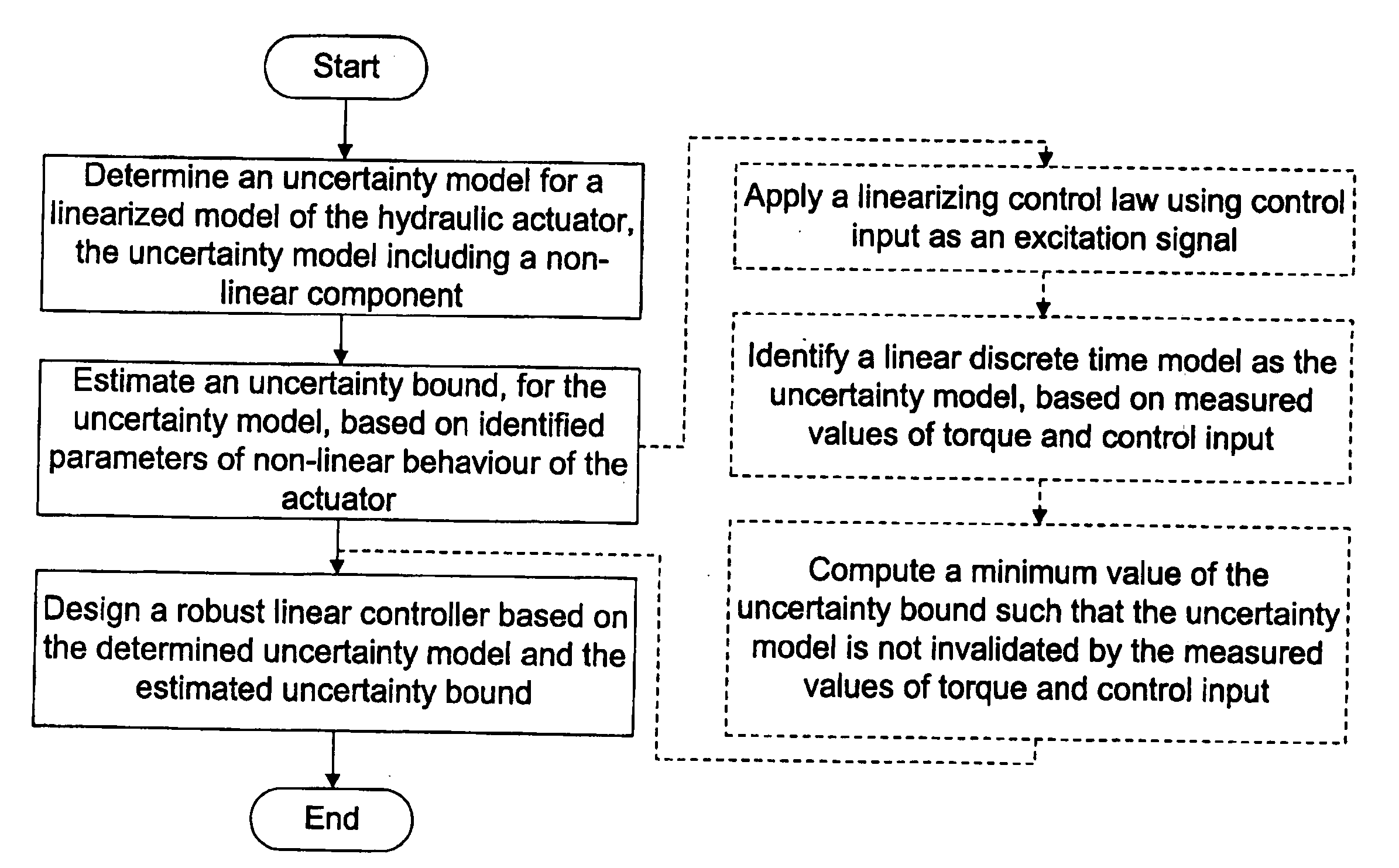
[0077] Case A
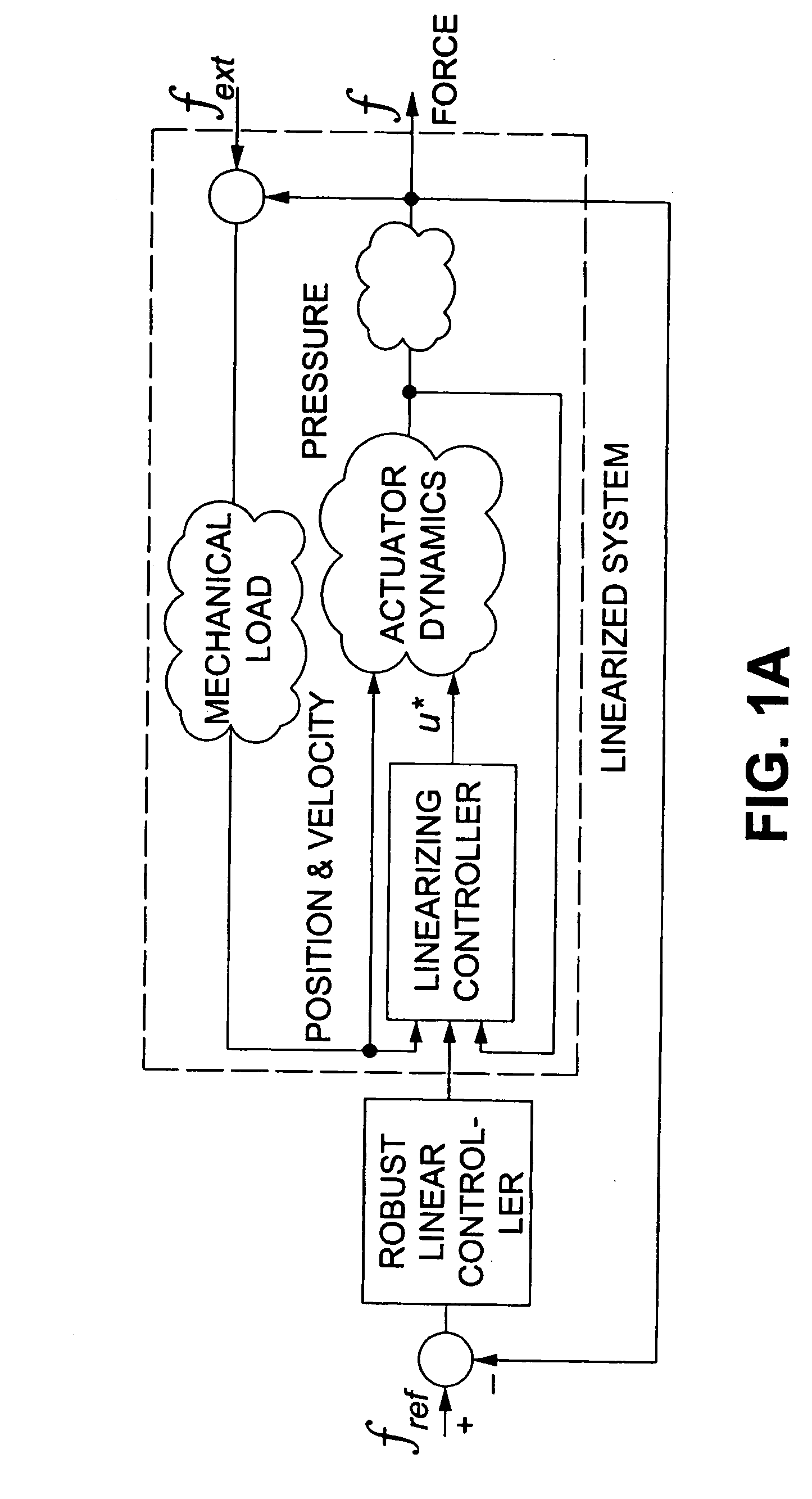
[0078]FIG. 3 is a block diagram of an uncertainty model structure according to an embodiment of the present invention, described as Case A. In particular, FIG. 3 illustrates an additive model structure, where Ĝ is a model for an integrator.
[0079] Assume that both the parametric and non-parametric uncertainty terms are bounded and that they can be represented by Y (p1,p2,x,ω,u) θ~+d (p1,p2,x,ω,u,t)=ⅆⅆt(Δ v+e (t))
where Δ is a bounded non-linear operator with ∥Δ∥1≦γ where the I1 norm of an operator like Δ mapping the signal x to the signal y, is defined by Δ1=supx≠oy∞x∞
with ∥x∥∞=supt|x(t)|. Moreover, e (t) represents any perturbation that is not a function of system states. Consequently, equation (12) becomes
τ=(D−1+Δ)ν+e(t) (13)
where D−1 is the integration operator.
[0080] It is observed that the operator Δ enters as an additive uncertainty to the integrator system. Now, the main problem is to compute an upperbound for this operator. The proposed meth...
case b2
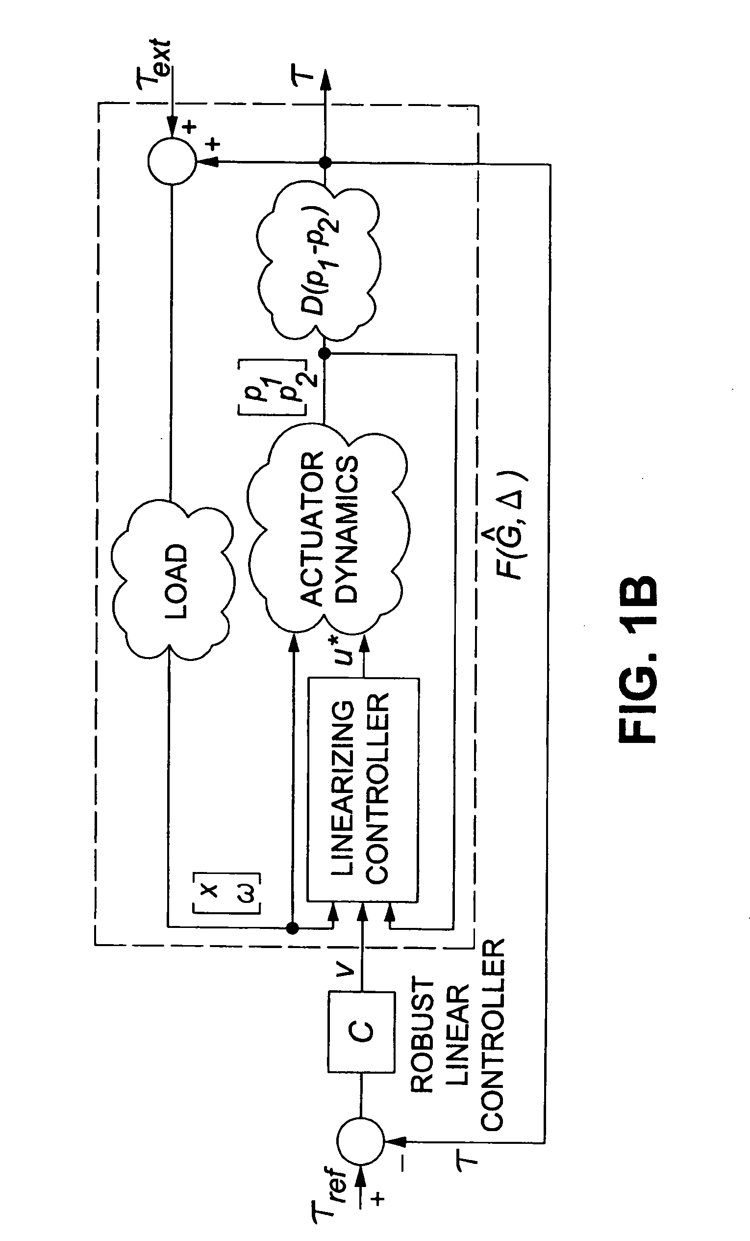
[0096] When Only β is Unknown and Load Dynamics are Unstable
[0097] Equation (20) can be written as
−1{dot over (τ)}=−1ν+Δτ+Δτext (22)
The following model structure is then proposed
Ĝ1τ=Ĝ2ν+Δτ+e (23)
where Ĝ1 represents a model for sL(s) and Ĝ2 is a model for L(s)−1. Obviously, Ĝ1 and Ĝ2 include load dynamics and hence, load dynamics is considered unknown. Similarly, e represents the term Δτext and it is bounded by ∥e∥∞≦∥Δ∥1∥τext ∥∞=γ∥τext∥∞.
[0098] The models Ĝ1 and Ĝ2 are parameterized as in (16) with parameter vectors {circumflex over (l)}1 and {circumflex over (l)}2, respectively. Therefore, given N+1 samples of ν, τ together with knowledge of ∥τext∥∞, the identification problem is to find {circumflex over (l)}1 and {circumflex over (l)}2 and minimum value ofγ such that the model structure (23) is not invalidated by data. The following linear programming can be similarly shown to solve the identification problem subject to: min γl^1.l^2,γTτF1l^1-TvF_2l^2≤γ(Eτ+...
case b1
[0107] Case B1
[0108] Given the model structure (21), the robust stability condition becomes WG^-11+G^-1C<γ-1(27)
[0109] Recalling that W=L it becomes clear that for the loads with high flexibility, the frequency response of W(jω) is large in some resonant frequencies. Therefore, constraint (27) requires that the closed loop sensitivity function G^-11+G-1C
be small in load resonance frequencies. This implies that when the effect of velocity is not perfectly eliminated by the linearizing controller, a limitation is imposed on the achievable performance through a robust stability constraint. This result is in accordance with known analysis describing the limitation effects of lightly damped modes of load on the achievable performance of force controllers. It is worthwhile to notice that these lightly damped modes affect the performance of our proposed controller only when the effect of velocity is not perfectly compensated. However, these modes limit the performance of typical P...
PUM
 Abstract
Description
Claims
Application Information