Gravity flow sludge load-out metering gate

Inactive Publication Date: 2003-01-21
RDP TECH
View PDF15 Cites 86 Cited by
  • Summary
  • Abstract
  • Description
  • Claims
  • Application Information

AI Technical Summary

Problems solved by technology

Further, because large and small municipalities and sewage districts have high sewage throughput and limited sludge storage capacity, the accumulation of sludge inventory cannot be tolerated.
It must be measured accurately because municipalities must charge customers for sludge actually delivered,

Method used


Image

  • Gravity flow sludge load-out metering gate
  • Gravity flow sludge load-out metering gate
  • Gravity flow sludge load-out metering gate

Examples


Embodiment Construction

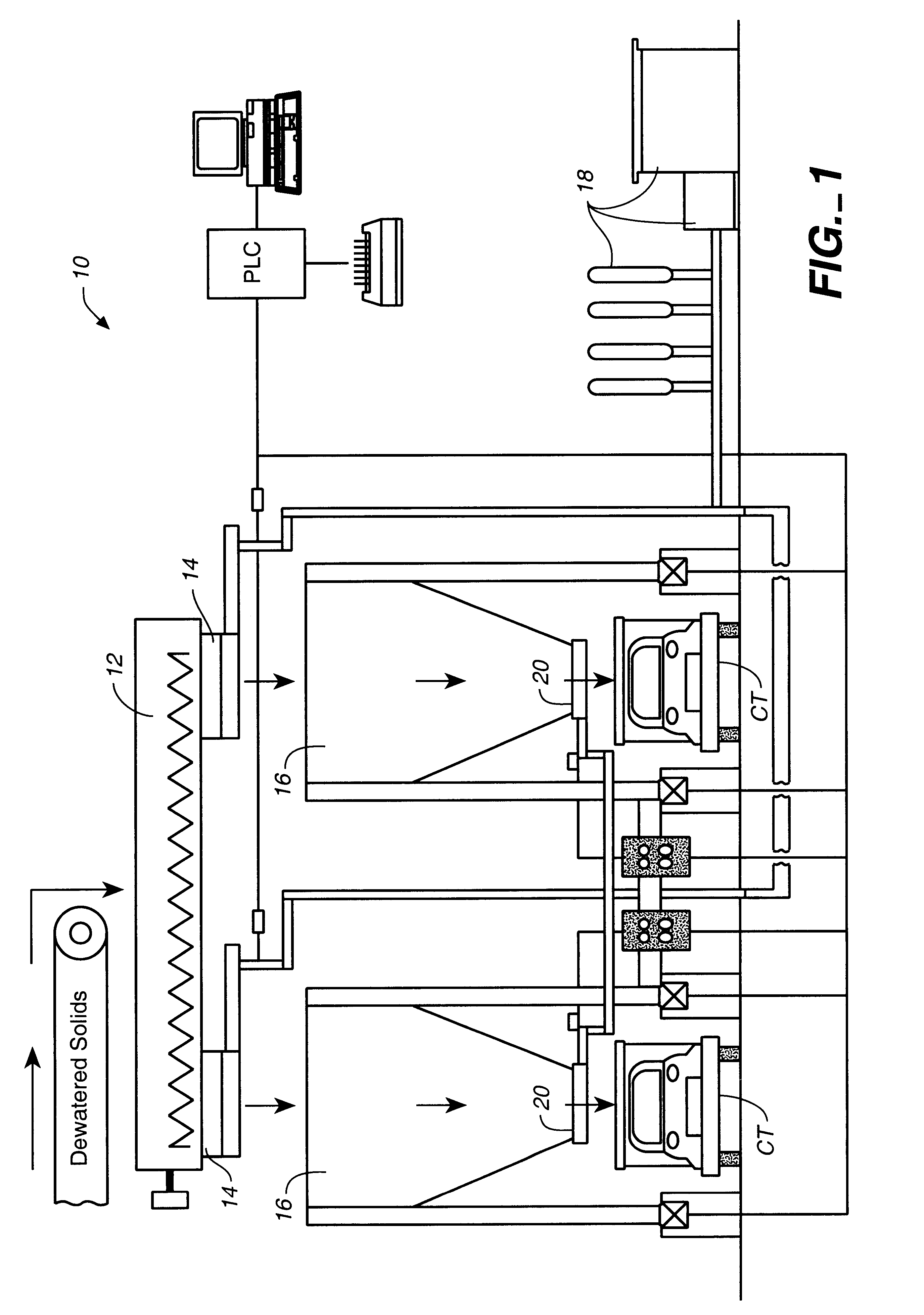
FIG. 1 is a side elevation schematic view of the environment of use of the gravity flow sludge load-out metering gate of the present invention. This view illustrates a dual station PLC controlled load-out system 10 wherein dewatered solids are conveyed from a dewatering plant (not shown) into a distribution container 12 and then through slide gates 14 into storage hoppers 16. The PLC may be programmed to control hopper loading and load-out and to modulate the position of control gates via a power system 18, which may be either hydraulic, pneumatic, or electric. The gravity flow sludge load-out metering gate of the present invention 20 is located at the base of each hopper and is positioned immediately above a container truck, CT, during a load-out sequence.

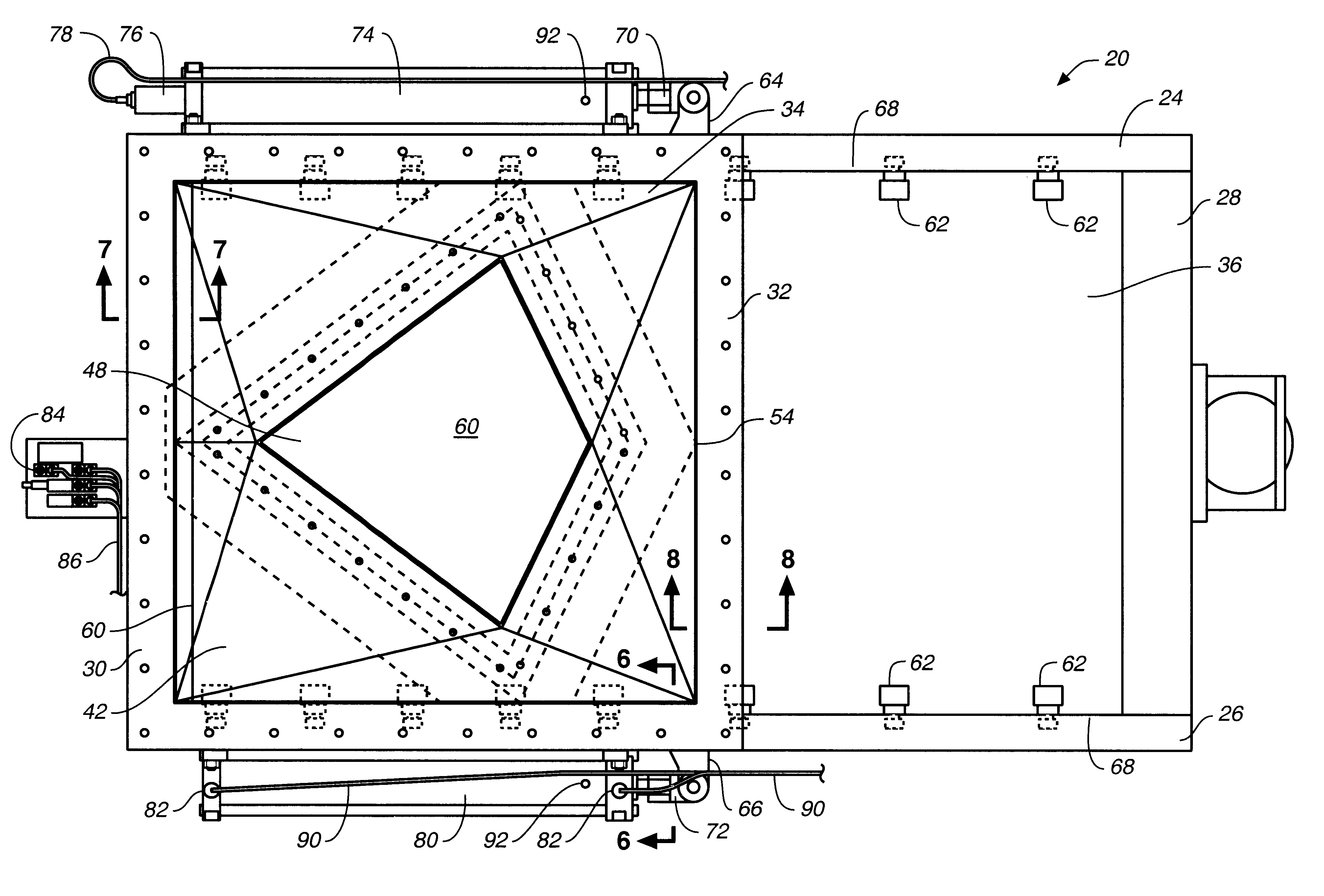
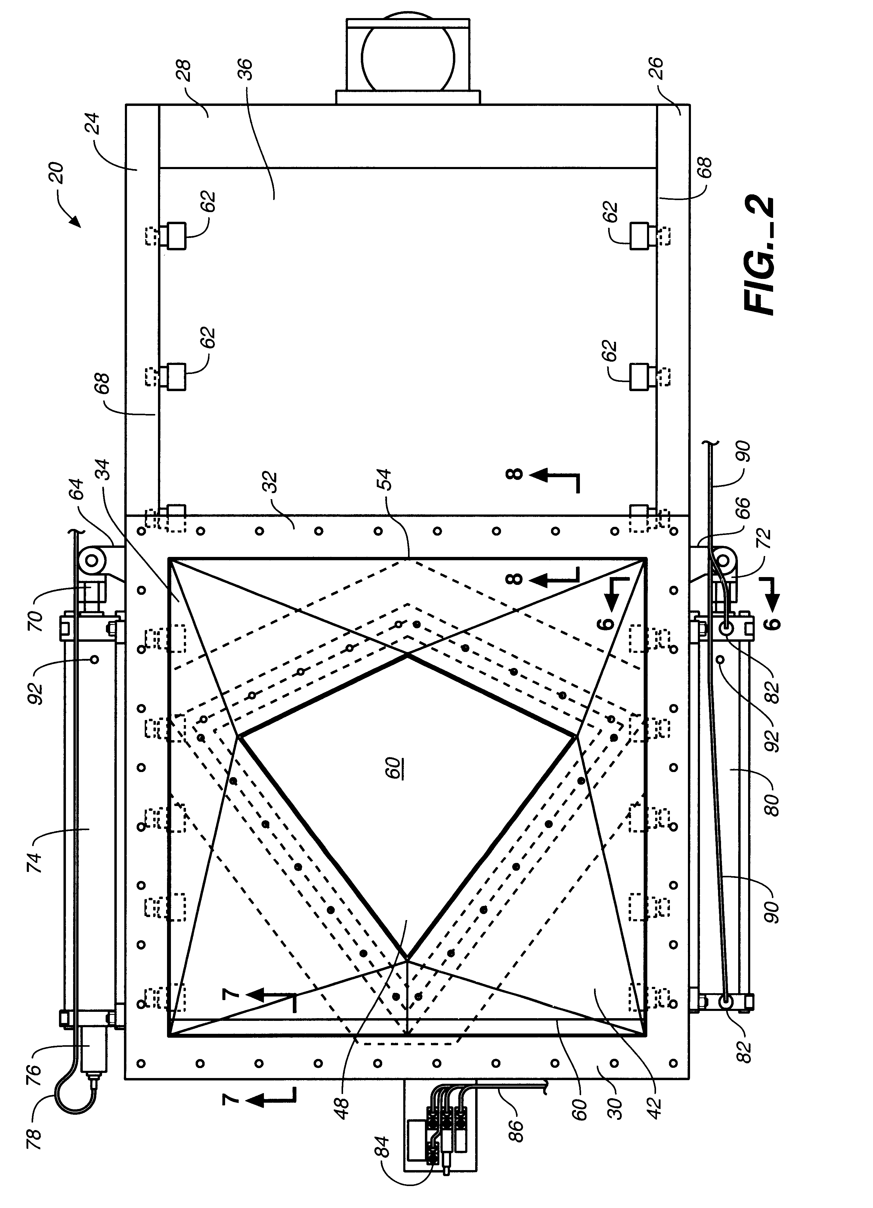
FIGS. 2 through 5 illustrate the static and dynamic elements of the gravity flow sludge load-out metering gate of the present invention. These views collectively show that the metering gate 20 generally comprises a substantially r...


PUM


Abstract

A gravity flow sludge load-out metering gate comprising a frame having longitudinal and horizontal frame rails and a transverse rail member which defines a gate front portion and a smaller gate rear portion. A sludge inlet funnel is positioned above the front portion for insertion into the interior of a hopper discharge outlet. In the preferred embodiment, the sludge inlet funnel is substantially square and has four triangular, tapering interior sides, which, when viewed from above define an asymmetrical four-pointed star, the interior configuration of which further defines an asymmetrical diamond-shaped sludge discharge orifice. Interior to the metering gate frame is a metering gate blade, slidingly positioned between a plurality of support rollers and a bulb seal, the gate operatively connected to electric, hydraulic, or pneumatic power.

Description

1. Cross Reference to Related ApplicationsNot applicable.2. Field of the InventionThe present invention relates generally to sludge load out gates, and more particularly to a gravity flow sludge load-out metering gate.3. Discussion of Related ArtIt is increasingly important for wastewater treatment facilities to provide an efficient and accurate system for sludge load-out. Because numerous methods have been devised to render biological sludge generally pathogen free and suitable for reuse as soil amendment and fertilizer, there is now a large demand for treated, dewatered biosolids, particularly by fertilizer manufacturers. Further, because large and small municipalities and sewage districts have high sewage throughput and limited sludge storage capacity, the accumulation of sludge inventory cannot be tolerated. Accordingly, it is imperative to have a sludge handling system that enables rapid load out into containers for transport either to sludge customers or to disposal sites.Such...

Claims


Application Information

Patent Timeline
IPC IPC(8): B65G53/46B65G53/40
CPCB65D90/587B65D90/66B65D2590/664B65D2590/0083Y10T137/8242
Inventor SIMON, RICHARD D.KINZEL, JERRY
Owner RDP TECH
Why Eureka
Try Eureka