Eureka AIR delivers breakthrough ideas for toughest innovation challenges, trusted by R&D personnel around the world.

Electrical connection terminal having a metal leaf spring actuated by a shift member and an elastic unit

a technology of electric connection and shift member, which is applied in the direction of coupling/disengagement, electrical apparatus, securing/insulating coupling contact members, etc., can solve the problems of slowing down the speed and hard to extract conductive wires from the main body

Active Publication Date: 2016-10-11
SWITCHLAB +1
View PDF9 Cites 16 Cited by
  • Summary
  • Abstract
  • Description
  • Claims
  • Application Information

AI Technical Summary

Benefits of technology

[0013]It is therefore a primary object of the present invention to provide an electrical connection terminal structure includes: a main body defining a chamber; a metal leaf spring disposed in the chamber, the metal leaf spring being movable with the motion of a shift member to press a conductive wire into electrical connection or release the conductive wire; and an elastic unit mounted in the chamber. When the metal leaf spring is released from the pressing of the shift member to release the conductive wire from the pressing, the elastic unit normally makes the metal leaf spring and the shift member move toward a position where the conductive wire is released. This improves the shortcoming of the conventional electrical connection terminal that when released, the metal leaf spring is apt to interfere with the conductive wire and make it hard to extract the conductive wire out of the main body.
[0015]In the above electrical connection terminal structure, the shift member is formed with a shoulder section. A damping section is disposed in the chamber of the main body corresponding to the shoulder section of the shift member. When the shift member is operated and pushed upward, the damping section frictionally interferes with the shoulder section to slowdown the speed by which the metal leaf spring elastically pushes the shift member. Therefore, the collision force applied by the shift member to the main body is reduced. This improves the problem of the conventional electrical connection terminal that the metal leaf spring will apply an elastic force to the shift member to make the shift member collide the main body to cause fissure or damage of the main body.

Problems solved by technology

This improves the shortcoming of the conventional electrical connection terminal that when released, the metal leaf spring is apt to interfere with the conductive wire and make it hard to extract the conductive wire out of the main body.
When the shift member is operated and pushed upward, the damping section frictionally interferes with the shoulder section to slowdown the speed by which the metal leaf spring elastically pushes the shift member.

Method used


Image

  • Electrical connection terminal having a metal leaf spring actuated by a shift member and an elastic unit
  • Electrical connection terminal having a metal leaf spring actuated by a shift member and an elastic unit
  • Electrical connection terminal having a metal leaf spring actuated by a shift member and an elastic unit

Examples


Embodiment Construction

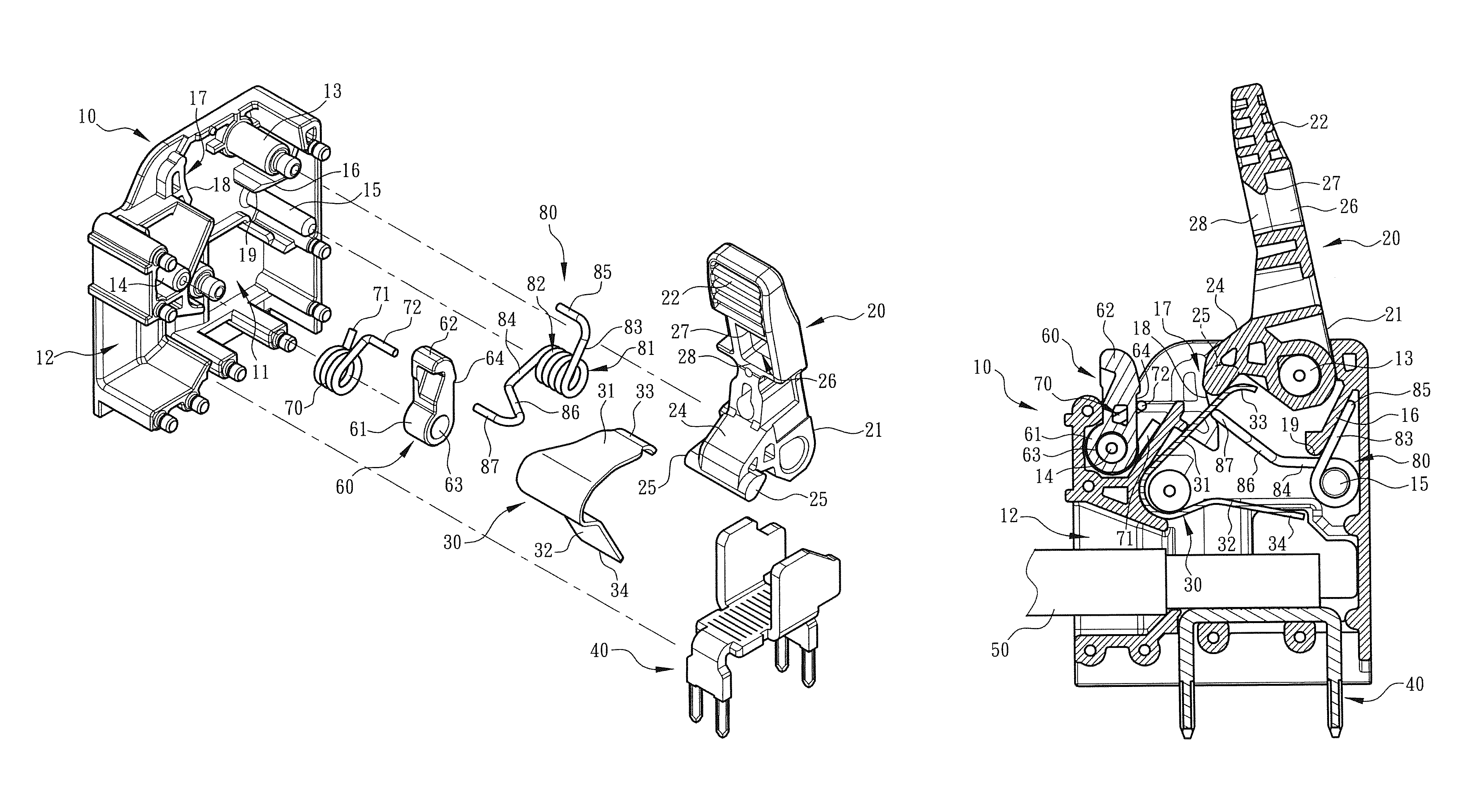
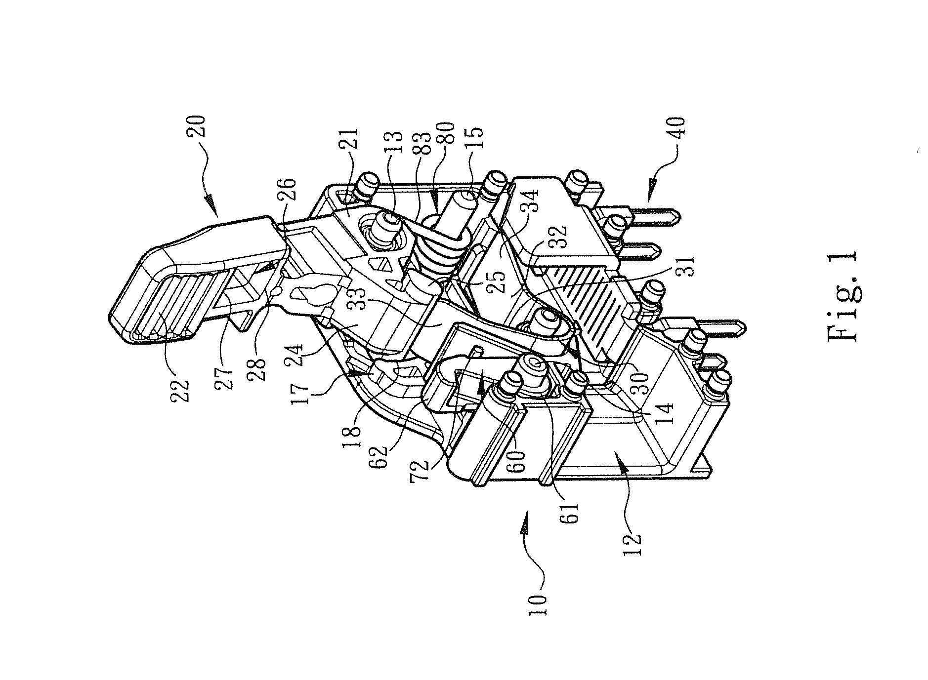
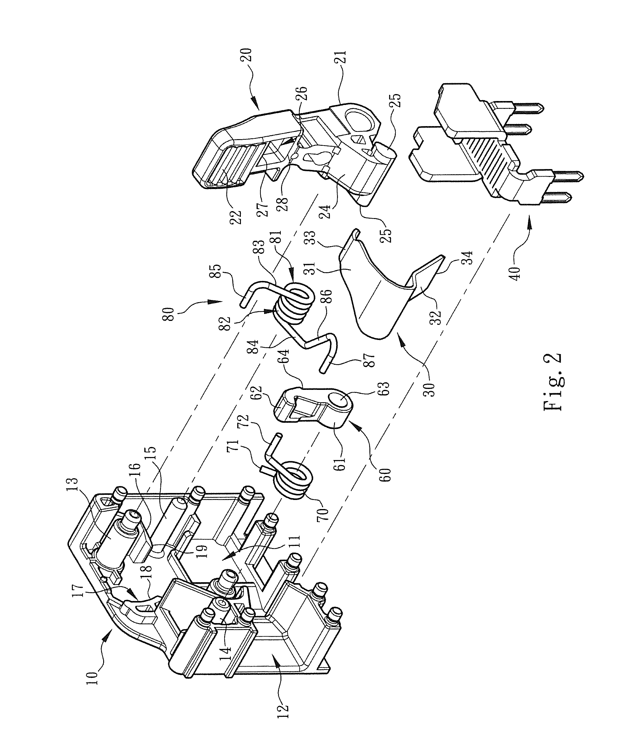
[0029]Please refer to FIGS. 1,2 and 3. The electrical connection terminal structure of the present invention includes a main body 10 made of insulation material and a shift member 20. The main body 10 defines a chamber 11. A metal leaf spring 30 and a terminal pin 40 are mounted in the chamber 11. The terminal pin 40 is for inserting on a circuit board (such as a PCB). The main body 10 includes a wire inlet 12 in communication with the chamber 11. A conductive wire 50 can be inserted into the chamber 11 through the wire let 12 to be pressed by the metal leaf spring 30, whereby the conductive wire 50 is electrically connected with the terminal pin 40.

[0030]In this embodiment, the metal leaf spring 30 is movable along with the motion of the shift member 20 to press the conductive wire 50 into electrical connection with the terminal pin 40 or release the conductive wire 50. To speak more specifically, the shift member 20 includes a pivoted end 21 and an operation end 22. The pivoted en...


PUM


Abstract

An electrical connection terminal structure includes: a main body defining a chamber; a metal leaf spring disposed in the chamber, the metal leaf spring being movable with the motion of a shift member to press a conductive wire into electrical connection or release the conductive wire; and an elastic unit mounted in the chamber. When the metal leaf spring is released from the pressing of the shift member to release the conductive wire from the pressing, the elastic unit normally makes the metal leaf spring and the shift member move toward a position where the conductive wire is released. This improves the shortcoming of the conventional electrical connection terminal that when released, the metal leaf spring is apt to interfere with the conductive wire and make it hard to extract the conductive wire out of the main body.

Description

BACKGROUND OF THE INVENTION[0001]1. Field of the Invention[0002]The present invention relates generally to an electrical connection terminal structure, and more particularly to an electrical connection terminal structure for an electrical conductive wire to insert and connect with. The an electrical connection terminal structure includes a main body, a shift member, an elastic unit and a metal leaf spring assembled with each other. The metal leaf spring is movable with the motion of the shift member to press the conductive wire or release the conductive wire.[0003]2. Description of the Related Art[0004]A conventional electrical connection terminal device or wire-pressing terminal has an insulation case (generally made of plastic material). A shift member is mounted on the case to control a metal leaf spring enclosed in the case to releasably press a conductive wire inserted in the terminal device into electrical connection. For example, EP 2325947 A1 discloses typical electrical con...

Claims


Application Information

Patent Timeline
Patent Type & Authority Patents(United States)
IPC IPC(8): H01R13/62H01R4/48H01R13/42
CPCH01R4/4836H01R13/42H01R4/4863H01R12/515H01R4/48365H01R4/48455
Inventor WU, CHIH-YUANCHEN, WEI-CHI
Owner SWITCHLAB
Why Eureka
Eureka Blog
Learn More