Personal air cooling visor clip-on

a technology of air cooling visor and clip-on, which is applied in the direction of headwear caps, non-positive displacement fluid engines, hats, etc., can solve the problems of frequent inconvenience for outdoor activities, and achieve the effect of convenient attachmen

Active Publication Date: 2016-11-08
COOK SR DON WHITNEY
View PDF5 Cites 9 Cited by
  • Summary
  • Abstract
  • Description
  • Claims
  • Application Information

AI Technical Summary

Benefits of technology

[0003]Persons involved in outdoor activities are frequently inconvenienced by the heat or non-moving air while participating or just being outside. The user has the convenience of receiving cool air whenever needed. The personal air cooling visor clip-on is powered through a usb cable receiving power from any usb power source, 5-volt battery pack / computer pack or computer. The clip-on attachment can be removed if desired when not needed. The clip-on strap rectangle plastic clip-on strap with an embedded 40×40×10 mm-5 volt battery pack / computer powered fan midway the length of clip-on strap has an appearance that is considered to be fashionable and can be left attached if desired.
[0004]The personal air cooling visor clip-on provides comfort, convenience and control of extended cooling to the face and forehead. The air cooling clip-on fan can be powered through convenience and inexpensive power sources using the universal usb connection that connects the fan to a usb 5-volt battery pack / computer power pack or to a computer through the usb port.
[0005]This invention is a device for attaching a rectangle plastic clip-on strap with an embedded 40×40×10 mm-5 volt battery pack / computer powered fan midway the length of clip-on strap on a cap having a brim projecting on a front side thereof over the wearer's face comprises: (a) a rectangle plastic clip-on strap with an embedded 40×40×10 mm-5 volt battery pack / computer powered fan midway the length of clip-on strap having on the top view side left and right side cap clams in a lengthwise direction thereof; (b) attaching means having left and right side cap clams for anchoring to the brim of the cap at positions substantially corresponding to the positions of the left and right side portions of the under-side of the cap when placed in an operative position with respect to said brim; (c) attachment means the left and right side cap clams attaching to the left and right side portions of the under brim of the operative position on the brim of the cap.
[0006]In the preferred embodiment, the attachment means left and right cap clams elements mounted on the top view left and right side of clip-on strap and attaching meaning under the cap brim so that embedded 40×40×10 mm-5 volt battery pack / computer powered fan midway the length of clip-on strap can be attached in an upward position out of the way of the wearer. The clip-on strap abuts against a stationary surface of the cap brim so as to provide detent positions for maintaining the clip-on strap stably in position when attached. The attachment means are provided with the cap clams for attaching to the brim of the cap. The pre-assembly is convenient for attachment by wearers to their own caps.
[0007]Other objects, features and advantages of the present invention are described in detail below in conjunction with the drawings, as follows:

Problems solved by technology

Persons involved in outdoor activities are frequently inconvenienced by the heat or non-moving air while participating or just being outside.

Method used


Image

  • Personal air cooling visor clip-on
  • Personal air cooling visor clip-on
  • Personal air cooling visor clip-on

Examples


first embodiment

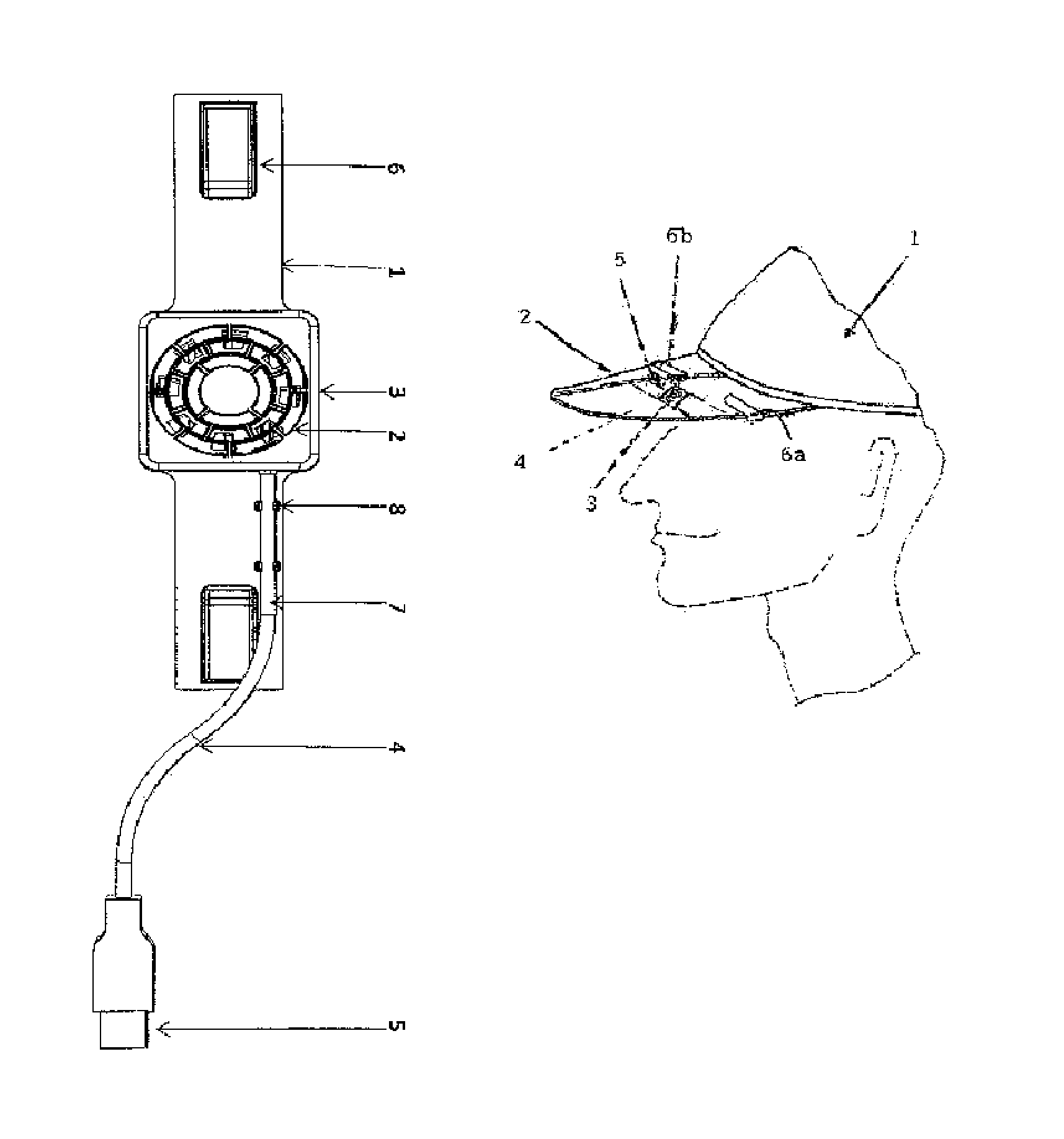
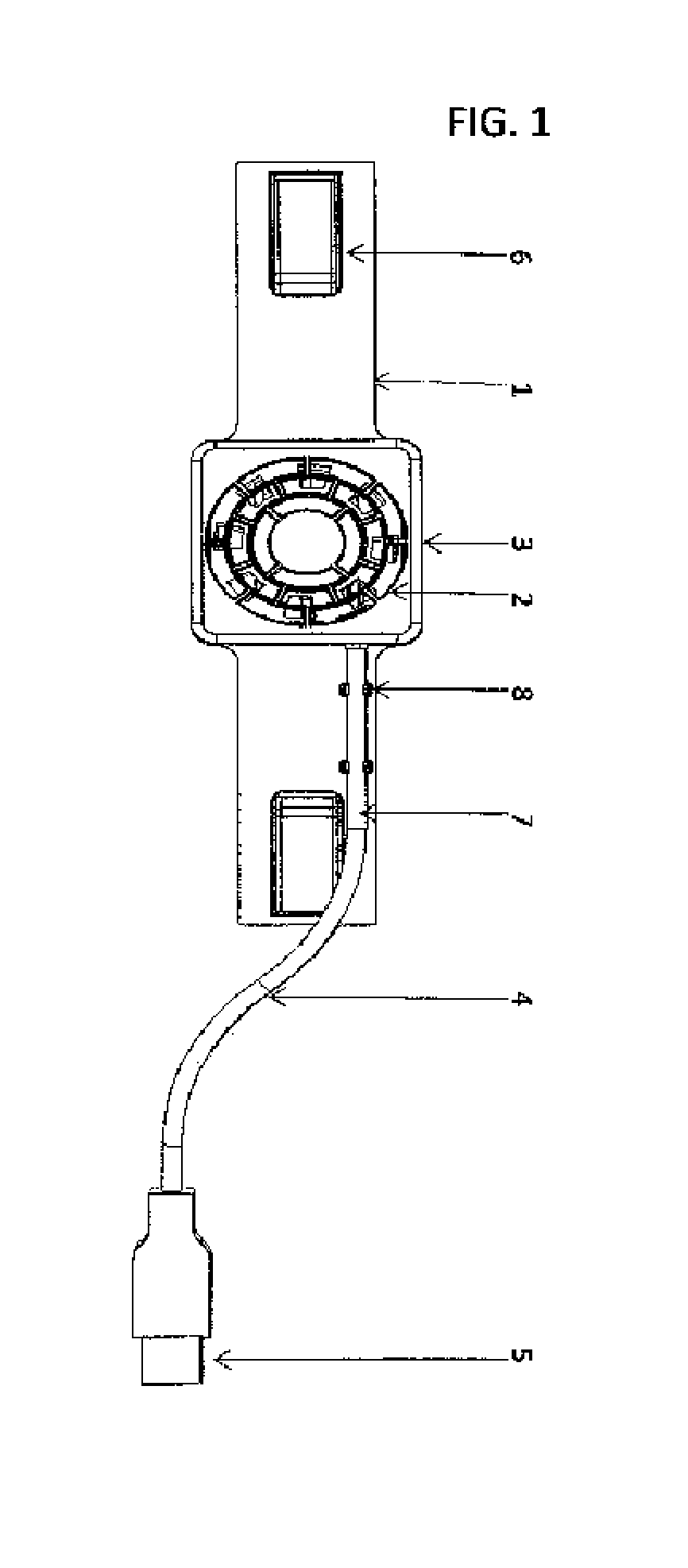
[0014]FIG. 1 is the device for attaching a rectangle plastic clip-on strap with an embedded 40×40×10 mm-5 volt battery pack / computer powered fan midway the length of clip-on strap to a cap. The preferred cap is of the type commonly referred to as a “baseball cap” having a cloth head portion 1 and a stiff brim 2 that extends frontward over the wearer's face. Baseball caps have a standard configuration and brim shape which allows the device to be dimensioned for attachment to and proper positioning on the brim. However, the principles disclosed herein can be readily adapted to other types of caps and hats, the only common requirement being that they have a stiff brim extending frontward over the wearer's face.

[0015]The device includes a rectangle plastic clip-on strap with an embedded 40×40×10 mm-5 volt battery pack / computer powered fan 3 midway the length of clip-on strap 5 fixed to an under brim 4 with left and right side portions. It extends in a widthwise direction across the widt...

second embodiment

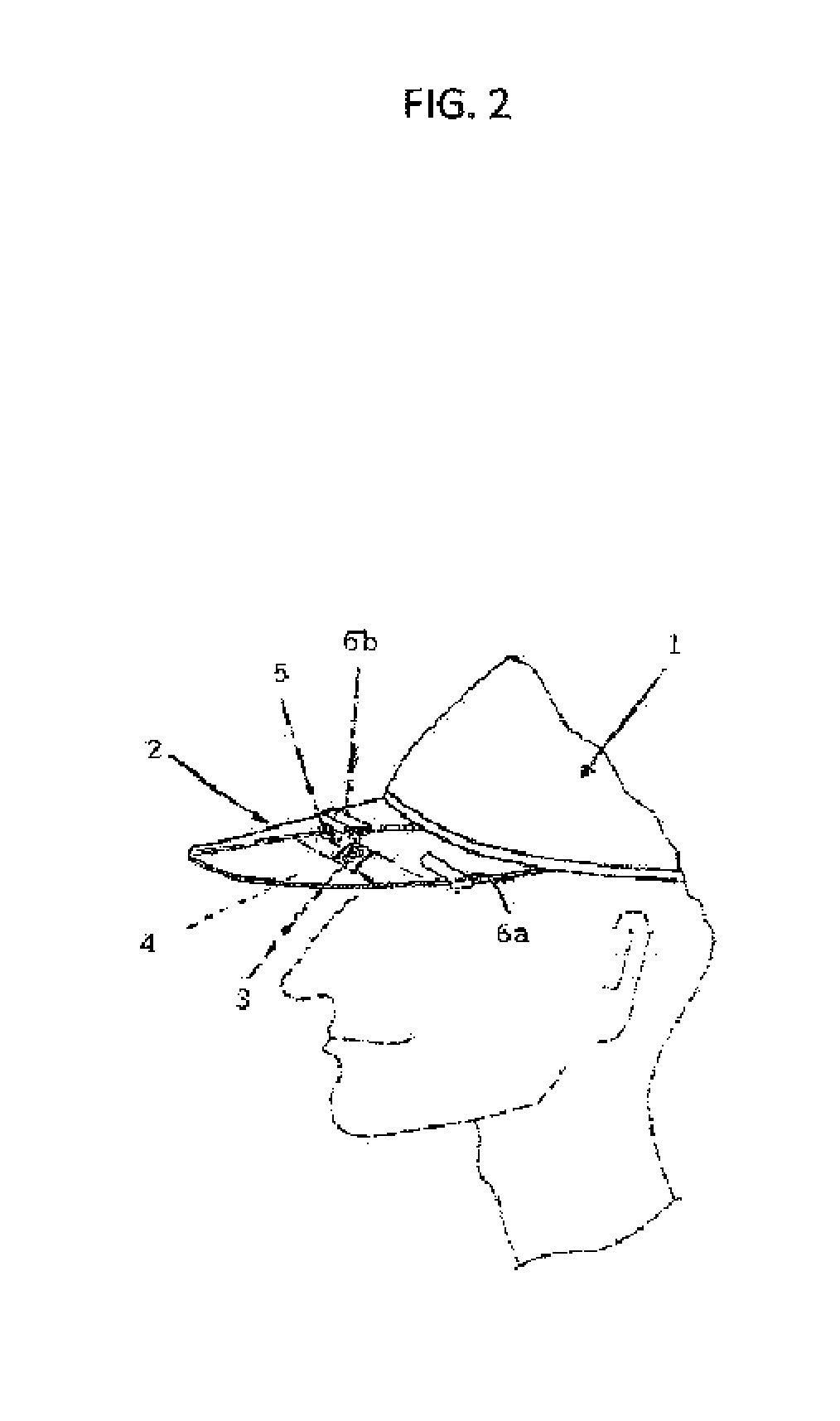
[0019]Thus, the rectangle plastic clip-on strap with an embedded 40×40×10 mm-5 volt battery pack / computer powered fan midway the length of clip-on strap will not be readily dislodged out of position unless positively pulled forward by the wearer. FIG. 2 is a second embodiment, bottom view of the device having rectangle plastic clip-on strap 1 with an embedded 40×40×10 mm-5 volt battery pack / computer powered fan 2 fixed (shown fitted in a groove) to the clip-on strap under brim notably held by the cover 3. The cable holding posts 8 are integrally formed. The clip-on strap clams 6 which are affixed on respective sides of the brim.

[0020]The 40×40×10 mm-5 volt battery pack / computer powered fan 2 is connected to a usb cable 4 with a usb connection 5 on the end which connects to a 5 v power source commonly used such as a computer or battery pack. The usb cable runs inside the cable holding channel 7 on the bottom view side of the rectangle plastic clip-on strap.

[0021]FIG. 3 is the bottom ...


PUM


Abstract

A device for attaching personal air cooling visor clip-on with a cooling 40×40×10 mm-5 volt battery pack/computer powered fan to cap or other head gear. The rigid rectangle plastic clip-on strap has holding cap clams, cable holding posts, 40×40×10 mm-5 volt fan, fan cable, fan cover, cable holding channel, usb wire and cable, fan cover tabs and fan tabs slots on the clip-on strap. The 40×40×10 mm-5 volt battery pack/computer powered fan is partially embedded into the plastic clip-on strap and secured by a fan cover using tabs with the connected fan and usb cables locking into and secured by channel holding posts in a channel. The strap is pushed onto a cap or headgear with the clams holding on top of the left and right top ends of the cap brim.

Description

FIELD OF THE INVENTION[0001]This invention attaches a rectangle plastic personal air cooling visor clip-on which has an embedded 40×40×10 mm-5 volt battery pack / computer powered fan midway the length of clip-on strap to a cap or other headgear with easy means for attaching or removing as needed by the wearer. The fan creates a continuous flow of air to the head and forehead of the wearer. The personal air cooling visor clip-on provides comfort, convenience and control of extended cooling to the face and forehead. The personal air cooling visor clip-on can be powered through convenience and inexpensive power sources using the universal usb connection that connects the fan to a usb 5-volt battery pack / computer power pack or to a computer through the usb port.DESCRIPTION OF THE PRIOR ART[0002]There are numerous technology powered headgear for the cooling of the head and face. Typical of these patents is U.S. Pat. No. 6,032,291 to Asenguah in March 2000.U.S. Pat. No. 4,680,815 July 1987...

Claims


Application Information

Patent Timeline
Patent Type & Authority Patents(United States)
IPC IPC(8): F04D25/08A42B1/24A42B1/00
CPCA42B1/24A42B1/008F04D25/084
Inventor COOK, SR., DON WHITNEY
Owner COOK SR DON WHITNEY
Why Eureka
Try Eureka