
False formwork for moulding concrete panels

a technology of false formwork and concrete, applied in the field of false formwork, can solve the problems of reducing the overall cost of moulding the panel, reducing the overall cost of the panel, and all the components of the waste produ

Active Publication Date: 2016-11-08
SRB CONSTR TECH
View PDF21 Cites 3 Cited by
  • Summary
  • Abstract
  • Description
  • Claims
  • Application Information

AI Technical Summary

Benefits of technology

Enables cost-effective and efficient casting of concrete panels with window or door openings, allowing for seamless finishes and reusability of formwork components, reducing the need for skilled labor and minimizing imprints on the cast face.

Problems solved by technology

Such a procedure would not be suitable for casting concrete panels which are to have window / door openings formed therein, one on top of the other, mainly due to formwork imprints being left on the cast face of the upper panel.
Another disadvantage with known timber false formwork is that all of its components become waste product due to the fact that they cannot be re-used for moulding another concrete panel.
Still further the installation of the timber false formwork must generally be carried out by a skilled person, e.g. a carpenter, which adds to the overall cost of moulding the panels.

Method used


Image

  • False formwork for moulding concrete panels
  • False formwork for moulding concrete panels
  • False formwork for moulding concrete panels

Examples


Embodiment Construction

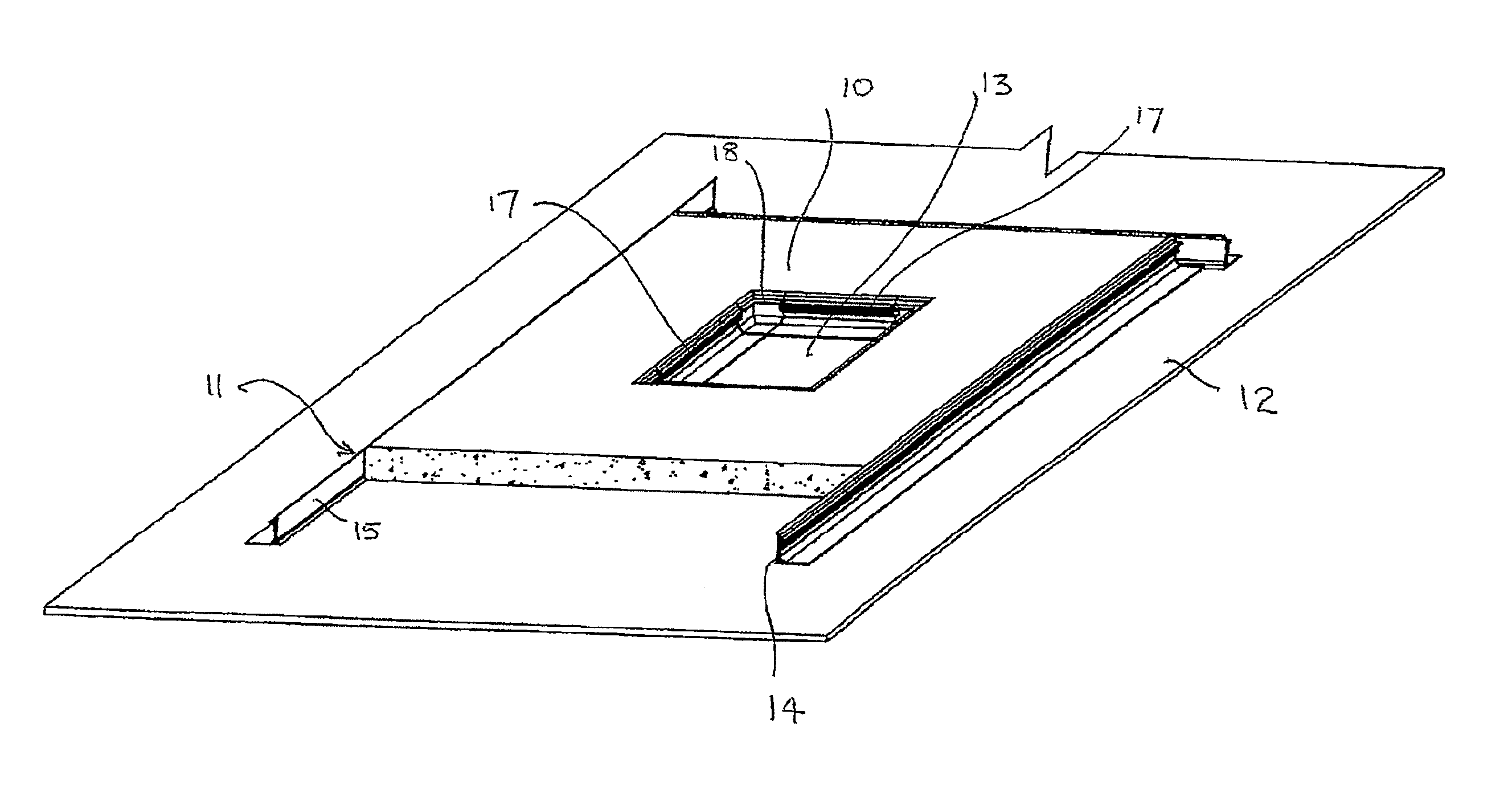
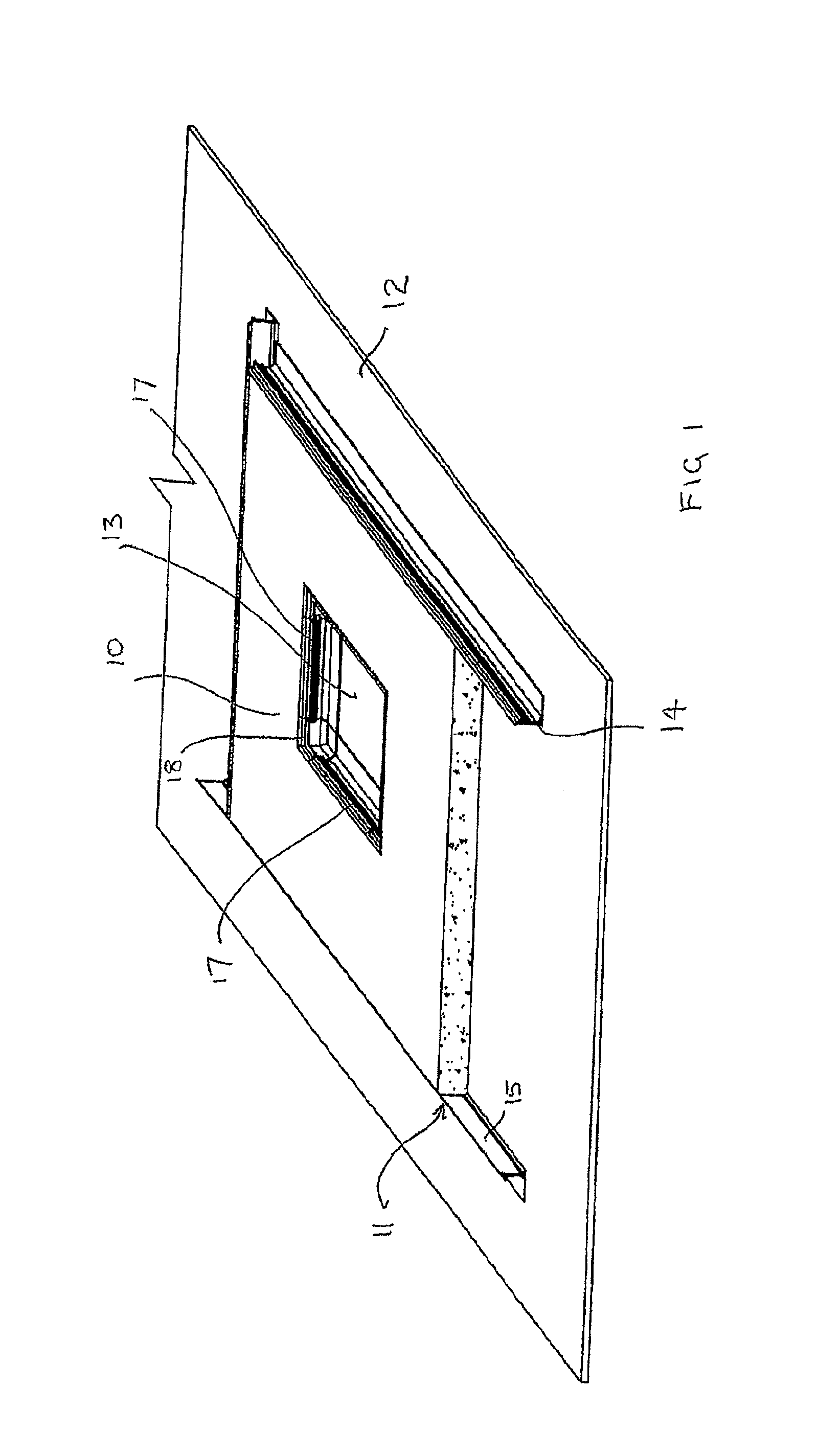
[0032]Referring initially to FIG. 1 of the drawings, reference numeral 10 generally designates a cast concrete panel. The panel 10 is formed by pouring concrete into a mould formed by a plurality of interconnected orthogonally arranged main sideforms 11 which are affixed by any suitable means to a base or bed 12. The bed 12 could be a base concrete panel in situations where concrete panels are cast one on top of the other.

[0033]A square or rectangular window opening is formed in the cast panel 10 using an embodiment of a false formwork system 40 of the invention. It will be appreciated that the false formwork system 40 of the invention could also be used for forming a door opening in the panel 10.

[0034]Each of the sideforms 11 is formed from an aluminium extrusion of angle section. A vertical flange 14 of the sideform 11 has fillets extending along the top and bottom edges of a face 15 of the vertical flange 14 of the sideform 11, so as to provide bevelled edge surfaces extending ar...


PUM

PropertyMeasurementUnit
heightaaaaaaaaaa

Abstract

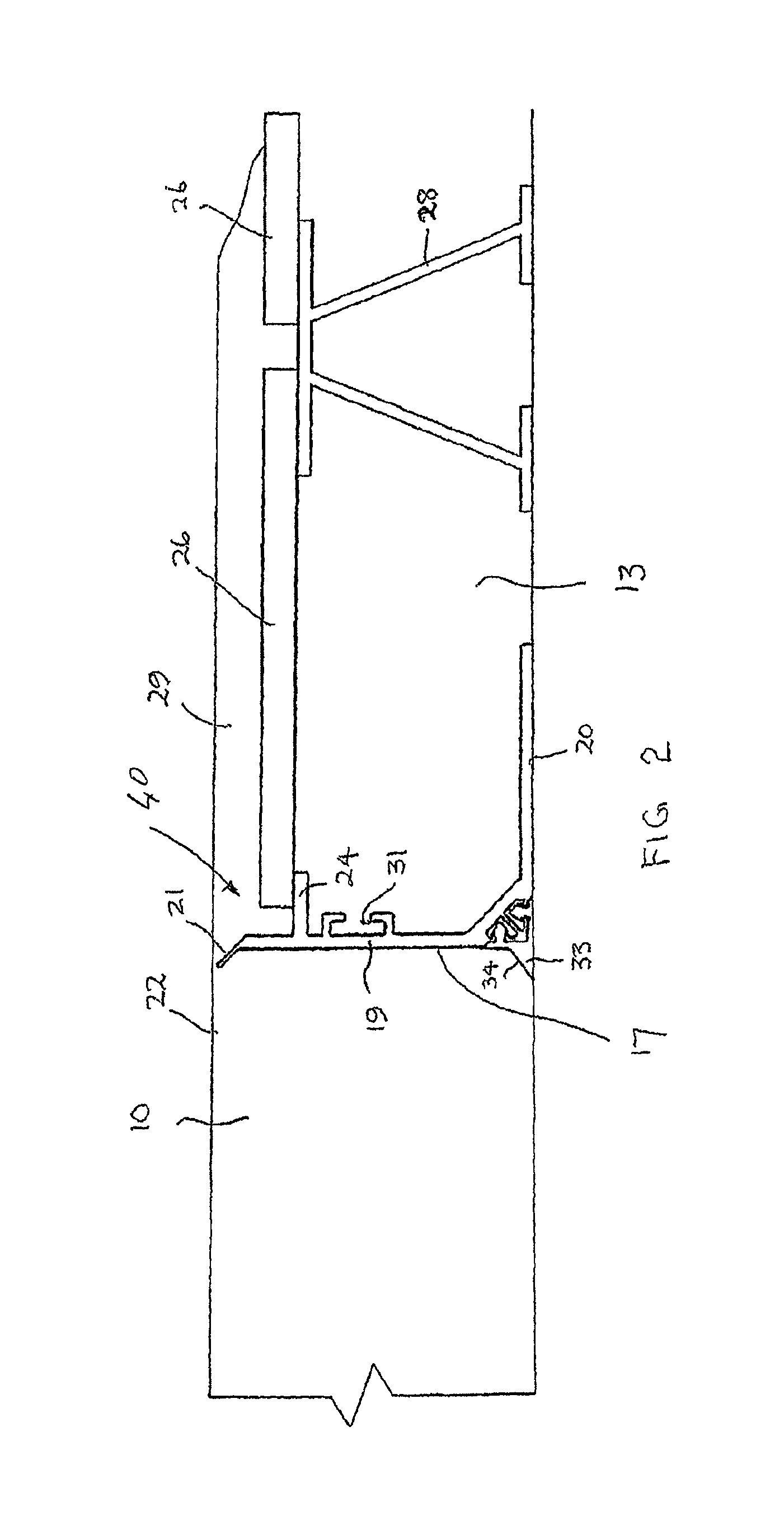
A false formwork system (40) includes a plurality of sideforms (17) which are able to be interconnected to define a perimeter of an opening in a panel to be cast. A support structure (24) is carried by the sideforms (17) for supporting components (26) used to mold a false skim coat overlying the opening when the panel is cast. An opening demarcation portion (21) is carried by each of at least some of the sideforms (17). Each opening demarcation portion (21) defines a zone of weakness to demarcate the skim coat of the cast panel from a remainder of the panel and to facilitate removal of the skim coat from the remainder of the panel by breakage along the zone of weakness.

Description

CROSS-REFERENCE TO RELATED APPLICATIONS[0001]This application is a divisional of U.S. patent application Ser. No. 12 / 514,257, filed on May 8, 2009, which is a National Stage of International Application No. PCT / AU2007 / 001654, filed on Oct. 31, 2007, which claims priority from Australian Patent Application No. 2006-906335, filed on Nov. 14, 2006, the contents of all of which are incorporated herein by reference in their entirety.FIELD OF THE INVENTION[0002]This invention relates to formwork for use in the construction of concrete panels, in particular tilt-up wall panels, where the panels are cast in a stack one on top of the other. More specifically, the invention relates to false formwork for producing tilt-up concrete wall panels in which window or door openings are formed and to a method of casting a concrete panel.BACKGROUND TO THE INVENTION[0003]In traditional formwork methods in the moulding of a concrete wall panel, in situations where a window or door opening is required to ...

Claims


Application Information

Patent Timeline
Patent Type & Authority Patents(United States)
IPC IPC(8): B28B23/00E04B2/84B28B7/00B28B7/16E04G15/02E04G11/06E04G21/02
CPCE04B2/84B28B7/0014B28B7/0085B28B7/0088B28B7/164E04G11/06E04G15/02E04G21/02E04G2011/067
Inventor SLADOJEVIC, ROBERT
Owner SRB CONSTR TECH
Learn More