Lens driving apparatus and method

a driving apparatus and lens technology, applied in the direction of mountings, dynamo-electric machines, instruments, etc., can solve the problems of unknown technique for stabilizing the moving speed of the lens, user unfamiliar feeling, etc., and achieve the effect of removing unfamiliar feeling in the manipulation of the user

Active Publication Date: 2016-11-22
FUJIFILM CORP
View PDF16 Cites 6 Cited by
  • Summary
  • Abstract
  • Description
  • Claims
  • Application Information

AI Technical Summary

Benefits of technology

[0009]In view of the foregoing problems, an object of the present invention is to provide a lens driving apparatus and method in which changes in a moving speed of a movable lens in a lens assembly are prevented to remove unfamiliar feeling in manipulation of a user.
[0021]Consequently, changes in a moving speed of a movable lens in a lens assembly are prevented to remove unfamiliar feeling in manipulation of a user, because a coil current through a coil in a voice coil motor can be corrected in consideration of a coil position.

Problems solved by technology

Unfamiliar feeling in manipulation of a user is likely to occur.
There is no known technique for stabilizing the moving speed of the lens in a structure where the moving range of the coil includes not only the center of the magnet but its end points.

Method used


Image

  • Lens driving apparatus and method
  • Lens driving apparatus and method
  • Lens driving apparatus and method

Examples


first embodiment

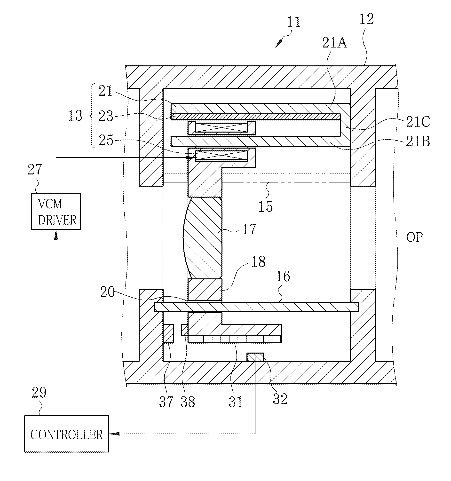
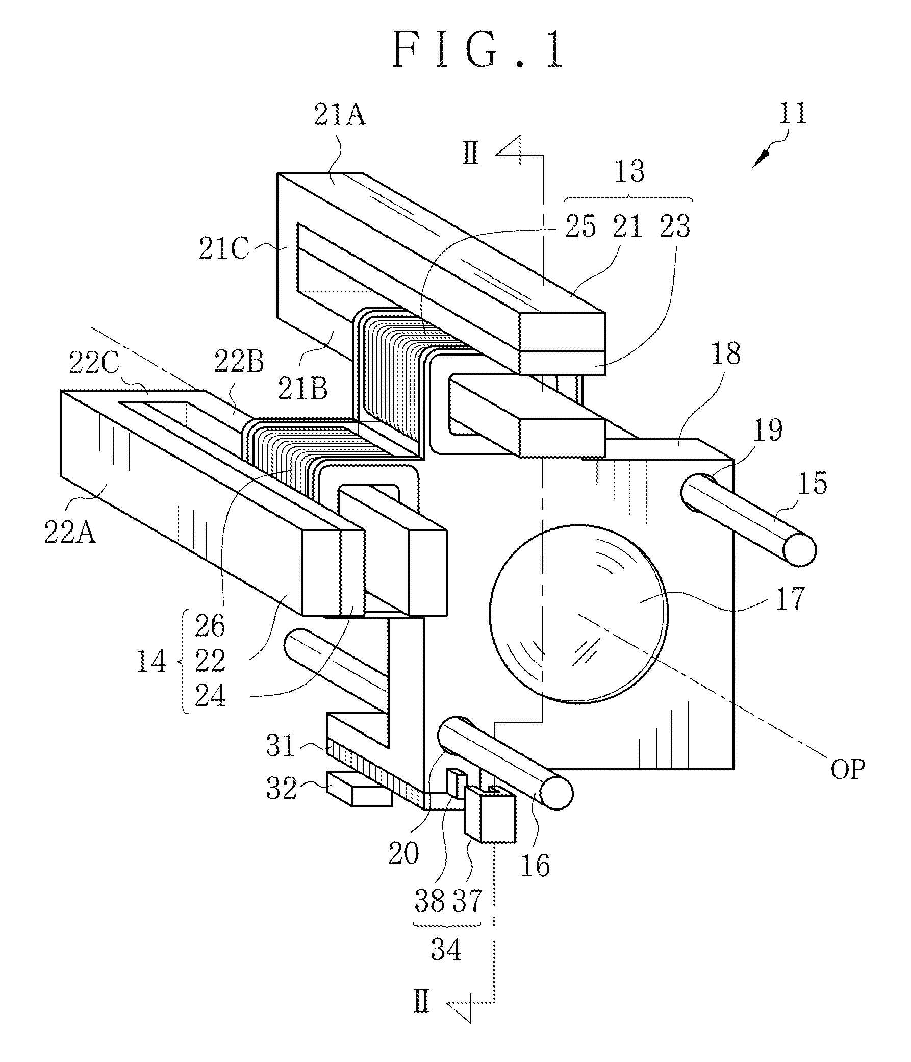
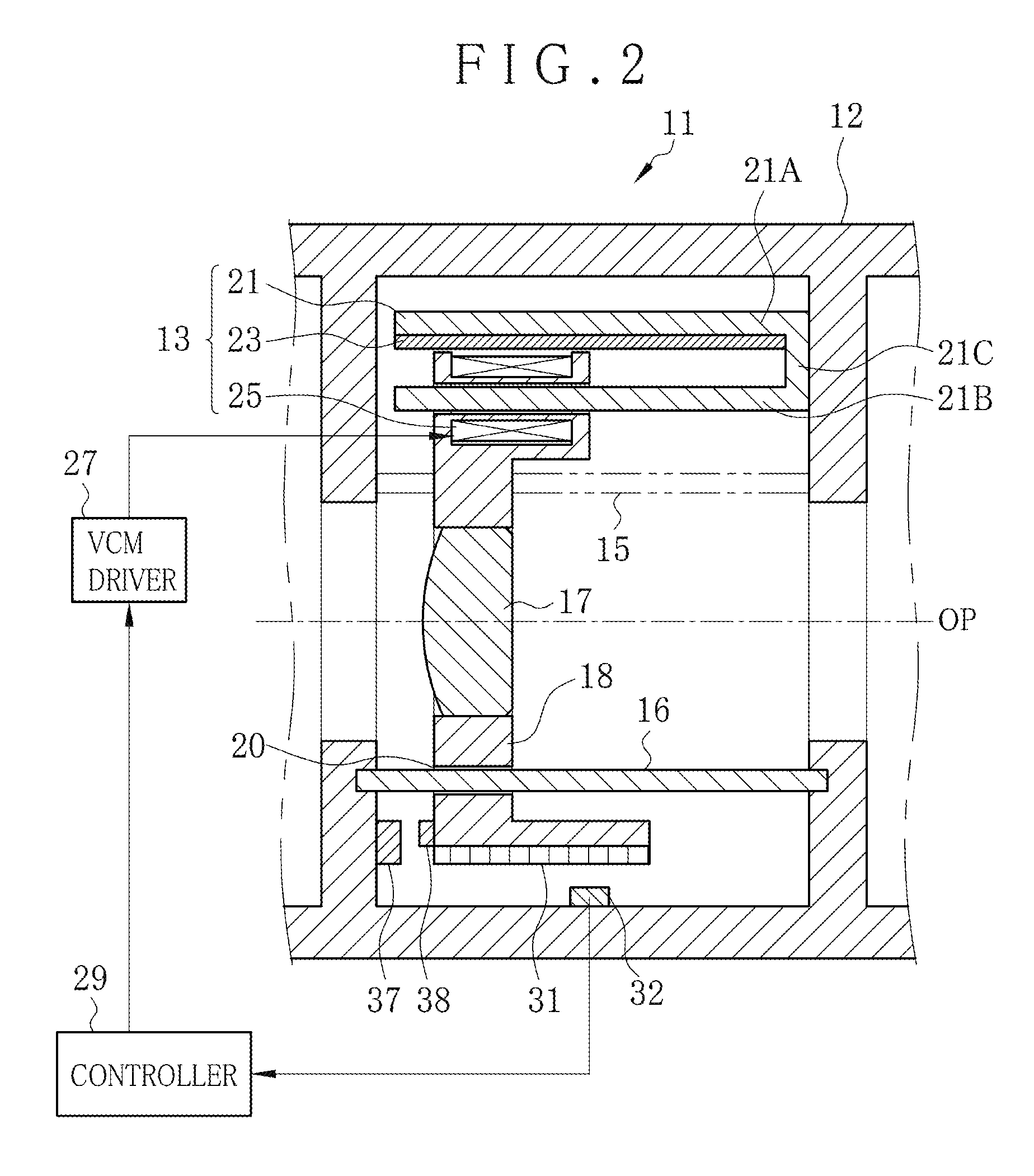
[0057]In FIGS. 1 and 2, a lens driving apparatus 11 (lens assembly) of a first embodiment of the invention is incorporated in a digital camera or the like for photographing an object. The lens driving apparatus 11 includes a lens barrel 12 of FIG. 2 and first and second voice coil motors 13 and 14 (VCMs). The lens barrel 12 includes guide rods 15 and 16, a lens 17 and a lens holder 18. The guide rods 15 and 16 are disposed in parallel with an optical axis direction OP and arranged in a rotationally symmetric manner about the optical axis direction OP.

[0058]A plurality of lenses (lens optics) are contained in the lens barrel 12. Among those, the lens 17 of the embodiment is a focus lens for adjusting the focus of the camera. The lens 17 may be a zooming lens (variator lens) as a component in a zoom lens assembly. Guide holes 19 and 20 are formed through the lens holder 18 in the optical axis direction OP. The guide holes 19 and 20 are arranged at corners of the lens holder 18 in a ro...

second embodiment

[0082]In FIG. 8, a second preferred lens driving apparatus 41 (lens assembly) is illustrated, and includes a temperature sensor 42 (temperature detector). A current is corrected by use of the first correction factor C1 and further corrected by use of a second correction factor C2. The temperature sensor 42 detects ambient temperature T around the magnets 23 and 24. The current is corrected by use of the second correction factor C2 corresponding to the detected temperature T. For the lens driving apparatus 41, the lens driving apparatus 11 is repeated but with a difference in having a system controller 43 (controller) and the temperature sensor 42. Elements similar to those of the above embodiments are designated with identical reference numerals.

[0083]An example of the temperature sensor 42 is a thermistor disposed inside the lens barrel 12, and detects the ambient temperature T around the magnets 23 and 24 to detect the temperature T of surfaces of the magnets 23 and 24 indirectly....

third embodiment

[0094]In FIG. 12, a third preferred lens driving apparatus 51 (lens assembly) includes a clock device 52 (elapsed time meter) for measuring elapsed time. A third correction factor C3 according to the elapsed time is used to correct the current. In the lens driving apparatus 51, the lens driving apparatus 11 is repeated but with a difference of having the clock device 52 and a system controller 53 (controller). Elements similar to those of the above embodiments are designated with identical reference numerals.

[0095]The clock device 52 measures elapsed time t from a reference time point of having measured the flux density distribution BD of the magnets 23 and 24. An example of the reference time point is a time point of having measured the flux density distribution BD of the magnets 23 and 24 in a condition predetermined in the manufacture. Assuming that the magnet is exchanged for repair or other purposes, the reference time point is a time point of measuring the flux density distrib...


PUM


Abstract

A lens driving apparatus for a lens includes a voice coil motor. A coil position of a coil is detected. A table memory stores a correction factor for each one of plural values of the coil position according to flux density distribution. The correction factor is read from the table memory according to the detected coil position. A coil current is corrected by use of the correction factor for each coil position. The corrected coil current is caused to flow through the coil, with which the lens is moved together along an optical axis. Consequently, changes in a moving speed of the lens can be prevented.

Description

CROSS-REFERENCE TO RELATED APPLICATION[0001]This application is a Continuation of PCT International Application PCT / JP2013 / 072662 filed on Aug. 26, 2013, which claims priority under 35 USC 119(a) from Japanese Patent Application No. 2012-217442 filed on Sep. 28, 2012. The above application is hereby expressly incorporated by reference, in its entirety, into the present application.BACKGROUND OF THE INVENTION[0002]1. Field of the Invention[0003]The present invention relates to a lens driving apparatus and method. More particularly, the present invention relates to a lens driving apparatus and method in which changes in a moving speed of a movable lens in a lens assembly are prevented to remove unfamiliar feeling in manipulation of a user.[0004]2. Description Related to the Prior Art[0005]A lens driving apparatus (lens assembly) is provided in a digital camera, video camera or the like for focusing, zooming and the like. An example of a motor in the lens driving apparatus is a voice c...

Claims


Application Information

Patent Timeline
Patent Type & Authority Patents(United States)
IPC IPC(8): H02K41/00G02B7/04G02B7/08H02K41/035G02B7/02
CPCG02B7/04G02B7/023G02B7/08H02K41/0356H02P25/034
Inventor SHIMOTSU, SHINICHI
Owner FUJIFILM CORP
Why Eureka
Try Eureka