
Device and method for checking the wear of roller chains

a technology of wear and measurement method, applied in measurement devices, plug gauges, instruments, etc., can solve the problems of inability to determine whether a chain is still serviceable or already too severely worn, measurement is inaccurate, and measurement is hardly possible with a fitted chain

Active Publication Date: 2016-12-06
HOEBEL GLENN +1
View PDF18 Cites 0 Cited by
  • Summary
  • Abstract
  • Description
  • Claims
  • Application Information

AI Technical Summary

Benefits of technology

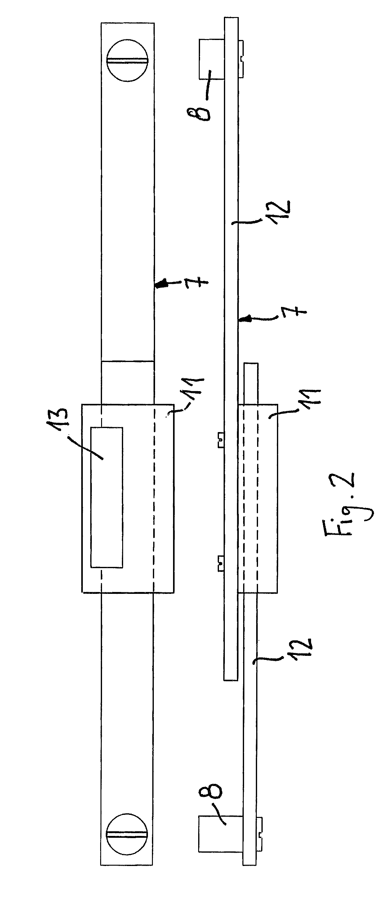
The invention is about a tool that can measure the space between different parts of a roller chain. This is done by using two tools, one to tension the chain and another to measure the spacing between different parts. This process is separate from the tensioning process, which ensures accurate results. The measurements are made at the link plates where the two tools touch, and not on the roller chain's upper or lower side. By using two contact pins on each link plate and a flat surface for fixation, the tool can measure wear on the chain accurately and easily. This makes it easy to measure the performance of a roller chain in its fitted state.

Problems solved by technology

This measurement is hardly possible with a fitted chain and is fairly inaccurate even if the chain has been removed.
It is also disadvantageous insofar as it is awkward to manufacture and can only be used for lightweight chains, such as bicycle chains.
Furthermore, it is only possible to determine whether a chain is still serviceable or already too severely worn.
Although a numerical value is obtained with this device, the measurement is inaccurate.
Plus, it is again impossible to transfer a defined measuring load to the chain with this device.
Here too, it is only possible to determine whether a chain is still serviceable or already too severely worn.
It is not possible to transfer a defined measuring load to the chain with this device.
The result is inaccurate.
A further disadvantage here is the need for a reference chain.

Method used


Image

  • Device and method for checking the wear of roller chains
  • Device and method for checking the wear of roller chains
  • Device and method for checking the wear of roller chains

Examples


Embodiment Construction

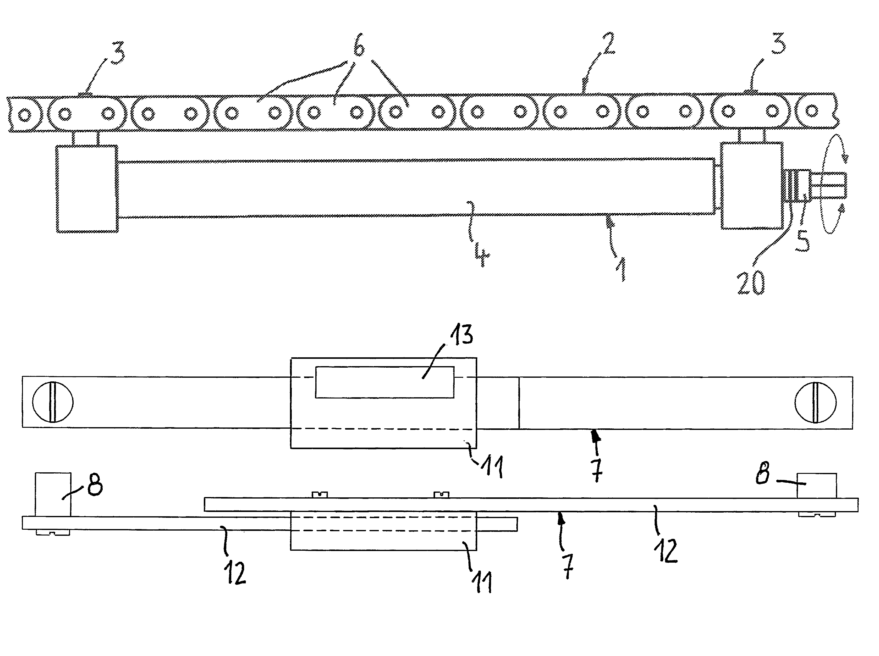
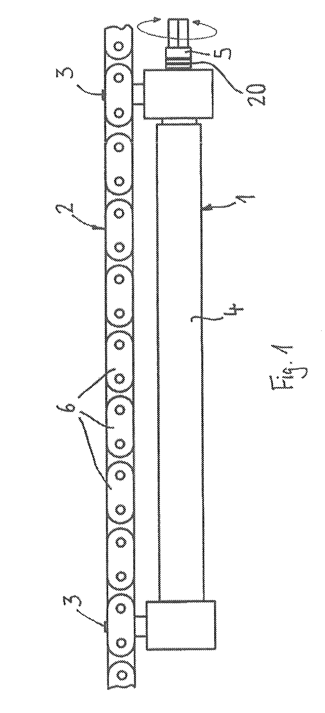
[0041]FIG. 1 shows the means 1 for tensioning a portion of the roller chain 2 with a defined measuring load, the tensioning means 1 having two pins 3, each of which can engage a chain opening, and a frame 4 connecting the two pins 3. The distance between the pins 3 is variable. In the example illustrated, the distance between the pins 3—and thus the measuring load applied to the roller chain 2—can be varied by rotating the adjusting member 5. The means 1 for tensioning a portion of the roller chain 2 can tension variously sized portions of the roller chain 2, the size depending on the maximum distance between the pins 3. It has proved advantageous if the portion includes approx. 20 chain links 6. It is useful that the measuring load applied to the roller chain in each case can be read off a marking 20.

[0042]Once a portion of the roller chain 2 has been tensioned with a defined measuring load, the spacing between a given number of chain links 6 within the tensioned portion is determi...


PUM


Abstract

A device and method of checking wear on roller chains enables a quantitative statement to be made about the state of wear of a fitted roller chain. A device for tensioning a portion of the roller chain with a defined measuring load and a device for measuring the spacing between a given number of chain links are provided, the device for measuring the spacing having two contact pins, each of which is configured for positioning between two rivet heads or on a rivet head of a link plate, and a device for measuring and displaying the distance between the two contact pins. An accurate, quantitative measurement of the wear on a roller chain in the fitted state is obtained quickly and easily.

Description

CROSS REFERENCE TO RELATED APPLICATIONS[0001]This application is the National Stage of PCT / DE2013 / 100018 filed on Jan. 21, 2013, which claims priority under 35 U.S.C. §119 of German Application No. 10 2012 100 436.6 filed on Jan. 19, 2012, the disclosure of which is incorporated by reference. The international application under PCT article 21(2) was not published in English.BACKGROUND OF THE INVENTION[0002]1. Field of the Invention[0003]The invention relates to a device and method of checking wear on roller chains, means being provided for tensioning a portion of the roller chain with a defined measuring load and means being provided for measuring the spacing between a given number of chain links.[0004]2. Description of the Related Art[0005]A gauge for measuring the spacing between two rivet heads of a chain is known from the U.S. Pat. No. 4,151,652 A and involves measuring the distance from the centre of one rivet head to the centre of the next rivet head. A defined measuring load ...

Claims


Application Information

Patent Timeline
Patent Type & Authority Patents(United States)
IPC IPC(8): G01B3/46G01B5/16G01B5/02
CPCG01B3/46G01B5/02G01B5/16
Inventor HOEBEL, GLENNBAYER, REINER
Owner HOEBEL GLENN
Learn More