Separation conveyance device, image forming apparatus, method for controlling separation conveyance device, and computer-readable recording medium

a technology of separation conveyance and separation device, which is applied in the direction of article separation, thin material handling, transportation and packaging, etc., can solve the problems of reducing the productivity of the apparatus, increasing the cost of the apparatus, and affecting the application of the technique to a sheet with an unknown thickness

Active Publication Date: 2016-12-13
RICOH KK
View PDF7 Cites 4 Cited by
  • Summary
  • Abstract
  • Description
  • Claims
  • Application Information

AI Technical Summary

Problems solved by technology

The delay of a sheet separation time leads to a reduction of productivity of the apparatus, for example.
This process, thus, causes a problem in that even if an error in sheet separation is detected the sheet may be conveyed so as to be subjected to image forming while being in the error state.
This, however, increases the cost of the apparatus.
The technique employing the overlapped feeding detection sensor using ultrasonic waves has a problem in that it is difficult for the technique to be applied to a sheet with an unknown thickness because the determination is performed on the basis of the measurement result of the thickness of the sheet.
In addition, the overlapped feeding detection sensor increases the cost of the apparatus.

Method used


Image

  • Separation conveyance device, image forming apparatus, method for controlling separation conveyance device, and computer-readable recording medium
  • Separation conveyance device, image forming apparatus, method for controlling separation conveyance device, and computer-readable recording medium
  • Separation conveyance device, image forming apparatus, method for controlling separation conveyance device, and computer-readable recording medium

Examples


first embodiment

[0038

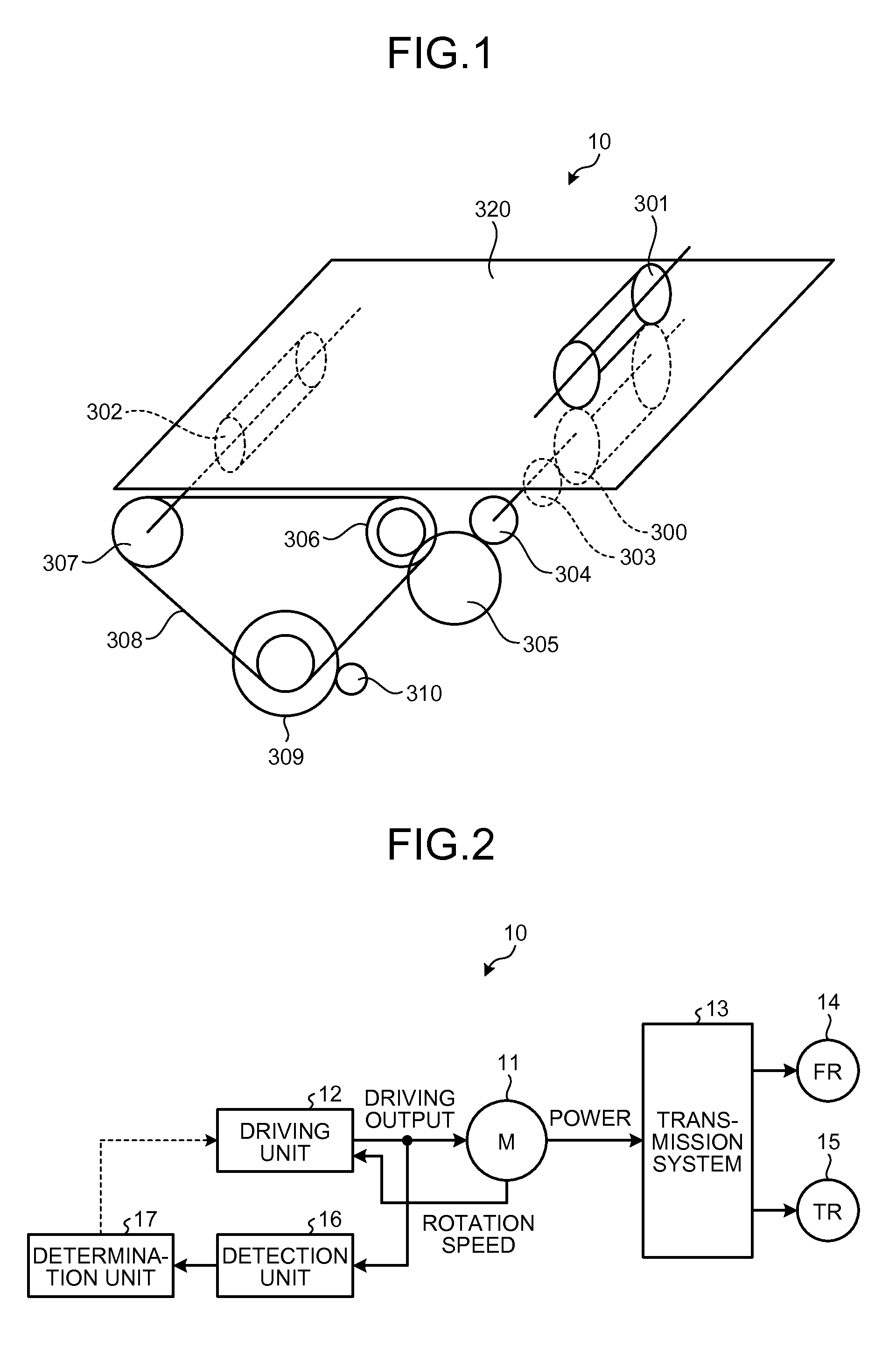
[0039]FIG. 1 is a schematic diagram schematically illustrating an exemplary structure of a separation conveyance device 10 applicable to a first embodiment. The structure illustrated in FIG. 1 is generally called a friction roller method, which is one of the separation conveyance methods. The separation conveyance device 10 feeds a sheet 320 serving as a conveyance object from a sheet bundle in which a plurality of sheets are stacked (not illustrated) and conveys the sheet 320. Here, the sheet is a sheet of paper. The sheet 320 is conveyed toward the left in FIG. 1.

[0040]As illustrated in FIG. 1, the separation conveyance device 10 includes a feed roller 300, a separation roller 301, and a conveyance roller 302, which are members directly in contact with the sheet 320. As illustrated in FIG. 1, the separation conveyance device 10 includes, as a structure of a driving transmission system that drives the feed roller 300 and the conveyance roller 302, a one-way clutch 303, a feed ...

second embodiment

[0166

[0167]The following describes a second embodiment of the present invention. The second embodiment is an example where the first embodiment is applied to a multifunction printer (MFP). The MFP is a multifunction peripheral that can achieve multiple functions such as a printer function, a scanner function, and a copying function in a single housing.

[0168]The MFP includes an image forming mechanism that forms an image on a sheet in accordance with image data and a scanner mechanism that reads an image from a document, for example. The MFP achieves the printer function, the scanner function, and the copying function in a single housing by combining or singly using the image forming mechanism and the scanner mechanism. The MFP can further include a communication unit that performs data communication, and further achieve a fax function by combining the printer function, the scanner function, the copying function, and the communication function of the communication unit.

[0169]FIG. 16 ...

third embodiment

[0233

[0234]The following describes a third embodiment of the present invention. In the third embodiment, the control of the conveyance system in the first embodiment is performed using the digital feedback control. In the third embodiment, the structures of the MFP 500 illustrated in FIG. 16 and the ADF 51 illustrated in FIG. 17 are used.

[0235]FIG. 19 illustrates an exemplary structure of a control system that controls the motor driving both of the driving roller 82 and the pullout roller pair 86 according to the third embodiment. A motor control circuit 1180 controls a motor 1110, which is a DC brushless motor. The motor control circuit 1180 includes a circuit 1181 for calculating target position and target speed, a circuit 1182 for performing following control of position and speed, and a circuit 1183 for calculating motor rotation amount and motor rotation speed.

[0236]A target signal generator 1190 in FIG. 19 produces a target signal in relation to a target rotation amount, a tar...


PUM


Abstract

A separation conveyance device comprises: a separation unit that includes a first roller feeding a conveyance object, and a load unit applying a load to the fed conveyance object, and separates one conveyance object from conveyance objects; a second roller that conveys the fed conveyance object; a driving unit that causes a motor to rotate the first roller at a first linear speed and the second roller at a second linear speed higher than the first linear speed; a connection unit that cuts off the motor's power from the first roller when first load torque toward a rotation direction of the first roller is equal to or larger than a certain value; a detection unit that detects second load torque in the direction opposite to a rotation direction of the motor; and a determination unit that determines a separation state of the conveyance object based on the second load torque.

Description

CROSS-REFERENCE TO RELATED APPLICATIONS[0001]The present application claims priority to and incorporates by reference the entire contents of Japanese Patent Application No. 2014-122663 filed in Japan on Jun. 13, 2014.BACKGROUND OF THE INVENTION[0002]1. Field of the Invention[0003]The present invention relates to a separation conveyance device, an image forming apparatus, a method for controlling the separation conveyance device, and a computer-readable recording medium.[0004]2. Description of the Related Art[0005]Image forming apparatuses such as printers and multifunction printers and image reading apparatuses such as scanners separate a sheet from stacked sheets and convey the separated sheet using feeding mechanisms or automatic document feeders (ADFs), for example. Sheet separation mechanisms used in such image forming apparatuses and image reading apparatuses are required to prevent the occurrences of non-feeding in which a sheet fails to be fed, overlapped feeding in which mul...

Claims


Application Information

Patent Timeline
Patent Type & Authority Patents(United States)
IPC IPC(8): B65H5/06B65H3/52B65H7/12
CPCB65H5/068B65H3/523B65H5/062B65H7/12B65H2403/42B65H2403/723B65H2511/524B65H2513/53B65H2515/32B65H2403/21B65H2220/01B65H2220/03B65H2513/52
Inventor YOSHIMIZU, EIKI
Owner RICOH KK
Why Eureka
Try Eureka