Permanent-magnet synchronous-motor position-free-sensor control method based on rotating-current vectors

A permanent magnet synchronous motor, current vector technology, applied in the field of electrical transmission, can solve the problems of increasing system complexity, poor observation accuracy, system adaptability and difficulty in operation and debugging, and achieve full-speed operation, low cost, guaranteed The effect of stability

Active Publication Date: 2014-02-26
ZHEJIANG UNIV
View PDF4 Cites 37 Cited by
  • Summary
  • Abstract
  • Description
  • Claims
  • Application Information

AI Technical Summary

Problems solved by technology

[0008] In order to solve the problem that the position sensorless control method of a single permanent magnet synchronous motor has poor observation accuracy in the high-speed section or low-speed section in the full-speed section, the existing main method is to use the position sensorless sensor suitable for the low-speed section and high-speed section Inductive control method is used for fusion, and the fusion positionless control method is used to solve the problem; now more methods are to use high-frequency signal injection method in the low speed section and use the back electromotive force method or model reference adaptive method in the medium and high speed section; and in the medium and low speed section Segment realizes smooth switching control of two algorithms
This will greatly increase the complexity of the system, and bring certain difficulties to the system's adaptability and operation debugging. Relatively accurate motor parameters are required, and the high-frequency signal injection method requires the motor to have a certain salient polarity. For the hidden pole Permanent magnet synchronous motors will no longer apply

Method used


Image

  • Permanent-magnet synchronous-motor position-free-sensor control method based on rotating-current vectors
  • Permanent-magnet synchronous-motor position-free-sensor control method based on rotating-current vectors
  • Permanent-magnet synchronous-motor position-free-sensor control method based on rotating-current vectors

Examples


Embodiment Construction

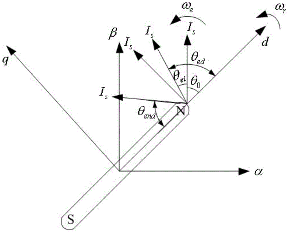
[0055] 1. Mathematical model of rotating current vector positionless starting

[0056] The technology of the present invention will be further described below in conjunction with the accompanying drawings, as can be known from the torque equation of the permanent magnet synchronous motor:

[0057] T e = 3 2 n p [ ψ f i q + ( L d - L q ) i d i q ] - - - ( 1 )

[0058] Assuming that the permanent magnet synchronous motor used is a surface-mounted permanent magnet synchronous motor, that is ...


PUM


Abstract

The invention relates to the field of electrical transmission and aims at providing a permanent-magnet synchronous-motor position-free-sensor control method based on rotating-current vectors. The method includes: setting the amplitude of the rotating-current vectors; setting the angle frequency of the rotating-current vectors; setting the position angle of a permanent-magnet synchronous-motor rotor; carrying out coordinate transformation on stator output current of a three-phase permanent-magnet synchronous motor; simulating PI operations of a d-p coordinate system; carrying out inverse transformation on coordinates and realizing whole driving via an inverter; and observing the power angle of the permanent-magnet synchronous motor. Starting of the permanent-magnet synchronous motor is completed after the above-mentioned seven steps are finished. The permanent-magnet synchronous-motor position-free-sensor control method based on the rotating-current vectors makes use of an inherent characteristic that under a condition that the permanent-magnet synchronous motor does not step out, the rotating speed of the rotor is capable of synchronously tracking of given frequency of a stator rotating magnetic field. The operation state of the permanent-magnet synchronous motor is observed through a load torque angle and controlled so that system stability is ensured. The method is low in cost, simple in control algorithm and capable of realizing full-speed-section operation of the permanent-magnet synchronous-motor position-free sensor perfectly.

Description

technical field [0001] The invention relates to a position sensorless control technology of a permanent magnet synchronous motor, which belongs to the field of electric transmission. Background technique [0002] Compared with induction motors, permanent magnet synchronous motors have advantages such as high torque / inertia ratio, high power density, and high efficiency. The permanent magnet synchronous motor rotor adopts permanent magnets, no excitation circuit, and the rotor has no excitation loss and iron loss, which simplifies the structure of the rotor, reduces the moment of inertia of the motor, and has higher efficiency and power factor of the motor. With the continuous improvement of the performance of rare earth permanent magnet materials and the maturity of permanent magnet synchronous motor control technology, permanent magnet synchronous motors are used in high-precision control fields such as CNC machine tools, robots, electric vehicles, and aerospace, as well as...

Claims


Application Information

Patent Timeline
Patent Type & Authority Applications(China)
IPC IPC(8): H02P21/00H02P27/08
Inventor 王海兵汤胜清赵荣祥杨欢
Owner ZHEJIANG UNIV
Why Eureka
Try Eureka