Image Formation Apparatus, Driving Control Method, And Computer Program Product

a technology of image formation apparatus and driving control method, applied in electrographic process apparatus, instruments, optics, etc., can solve the problems of image degradation, large number of torque variation profiles, and considerably difficult to select the optimal profile for each image formation process

Inactive Publication Date: 2012-06-28
RICOH KK
View PDF6 Cites 37 Cited by
  • Summary
  • Abstract
  • Description
  • Claims
  • Application Information

AI Technical Summary

Problems solved by technology

In such an image formation apparatus, an impact that occurs when the recording medium enters the transfer nip momentarily causes, to the image carrier, a large load torque that causes a change in the surface moving velocity of the image carrier to result in image degradation.
However, there has been a problem in the conventional image formation apparatus that exerts a braking force (driving load torque) on the driving source in advance and reduces or removes the braking force when a recording medium is going to enter the transfer nip so as to suppress a variation in the surface moving velocity of the image carrier, as described below.
For these reasons, in many cases, an actual torque variation profile occurring when the recording medium enters the transfer nip does not match the torque variation profile obtained by the prior measurement.
Even if every torque variation profile that is anticipated to occur in the actual image formation process can be prepared, it is considerably difficult to select a profile optimum to each image formation process from the thus-prepared large number of torque variation profiles.
As described above, the conventional image formation apparatus that tries to cancel a torque variation in the driving source occurring when a recording medium enters the transfer nip on the basis of the torque variation profile prepared in advance cannot cope with all the actual torque variation profiles that vary from one image formation process to another depending on the various kinds of factors.
Thus, in many cases, the conventional image formation apparatus is unable to cancel the torque variation of the image carrier with sufficient accuracy or to suppress a variation in the surface moving velocity of the image carrier.
Meanwhile, it is difficult to directly detect the position of a leading-end of the recording medium that enters the transfer nip.
Accordingly, if a conveying velocity of the recording medium differs from a target conveying velocity, an error occurs in the timing, determined by the detection result with the sensor, for the recording medium to enter the transfer nip.
A detection error of the sensor or an assembly error of the sensor also causes an error in the timing for the recording medium to enter the transfer nip according to the determination by the detection result with the sensor.
Such an error makes it difficult to detect the timing when the recording medium enters the transfer nip with high accuracy.
Therefore, in many cases, the conventional image formation apparatus, for which it is necessary to detect timing when a recording medium enters the transfer nip, fails to cancel the torque variation of the image carrier with sufficiently high accuracy, and hence cannot reduce the variation in the surface moving velocity of the image carrier.
A control method, which is typically employed in a conventional image formation apparatus, of obtaining a torque variation profile by a prior measurement and performing braking control based on the torque variation profile so as to cancel torque variation of an image carrier is primarily incapable of canceling torque variation of an image carrier caused by an impact whose occurrence is unpredictable or unable to be predicted with high accuracy.
Even for an impact whose occurrence is predictable with high accuracy, if a profile of torque variation in the image carrier caused by the impact is irregular, the torque variation cannot be cancelled with high accuracy.
However, according to such a control method, it is necessary to apply an additional driving torque that corresponds to a driving load torque to be caused by an impact during when the impact is not applied to the image carrier.
Accordingly, this control method, requiring a driving source of an image carrier to generate the additional driving torque, is disadvantageous in increasing power consumption.
Accordingly, the control method is also disadvantageous in that it is necessary to determine, in advance, a driving load torque to be caused by a real impact.

Method used


Image

  • Image Formation Apparatus, Driving Control Method, And Computer Program Product
  • Image Formation Apparatus, Driving Control Method, And Computer Program Product
  • Image Formation Apparatus, Driving Control Method, And Computer Program Product

Examples


first embodiment

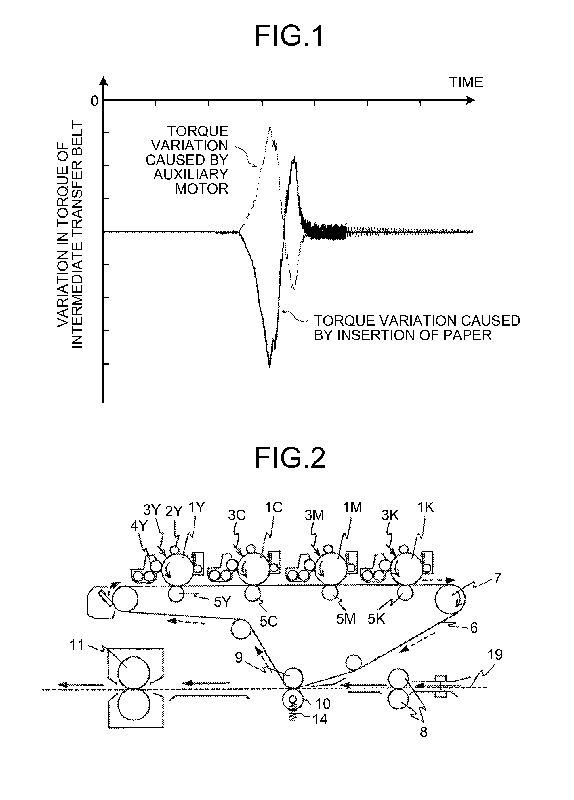
[0038]An embodiment (hereinafter, the present embodiment is referred to as a “first embodiment”), in which the present invention is applied to a copying machine serving as an image formation apparatus, will be described below.

[0039]FIG. 2 is a schematic configuration diagram illustrating an image formation unit of the copying machine according to the first embodiment. The copying machine is a tandem type image formation apparatus that includes a photosensitive element as an image carrier for each of colors including yellow (Y), cyan (C), magenta (M), and black (K). In FIG. 2, one of Y, C, M, and K, each of which is a color-distinguishing symbol to indicate a color of a member, is added to a reference symbol that is assigned to the member with the corresponding color; however, members different in colors have a substantially identical configuration to each other. Accordingly, the color-distinguishing symbols are omitted from the reference symbols in the explanations below.

[0040]A pho...

second embodiment

[0099]Another embodiment (hereinafter, referred to as “second embodiment”) when the present invention is applied to a copying machine serving as the image formation apparatus will be described below as in the first embodiment.

[0100]The second embodiment is similar to the first embodiment with a difference from the first embodiment only in that the velocity of the intermediate transfer belt 6 is to be detected. Therefore, only the difference will be described below.

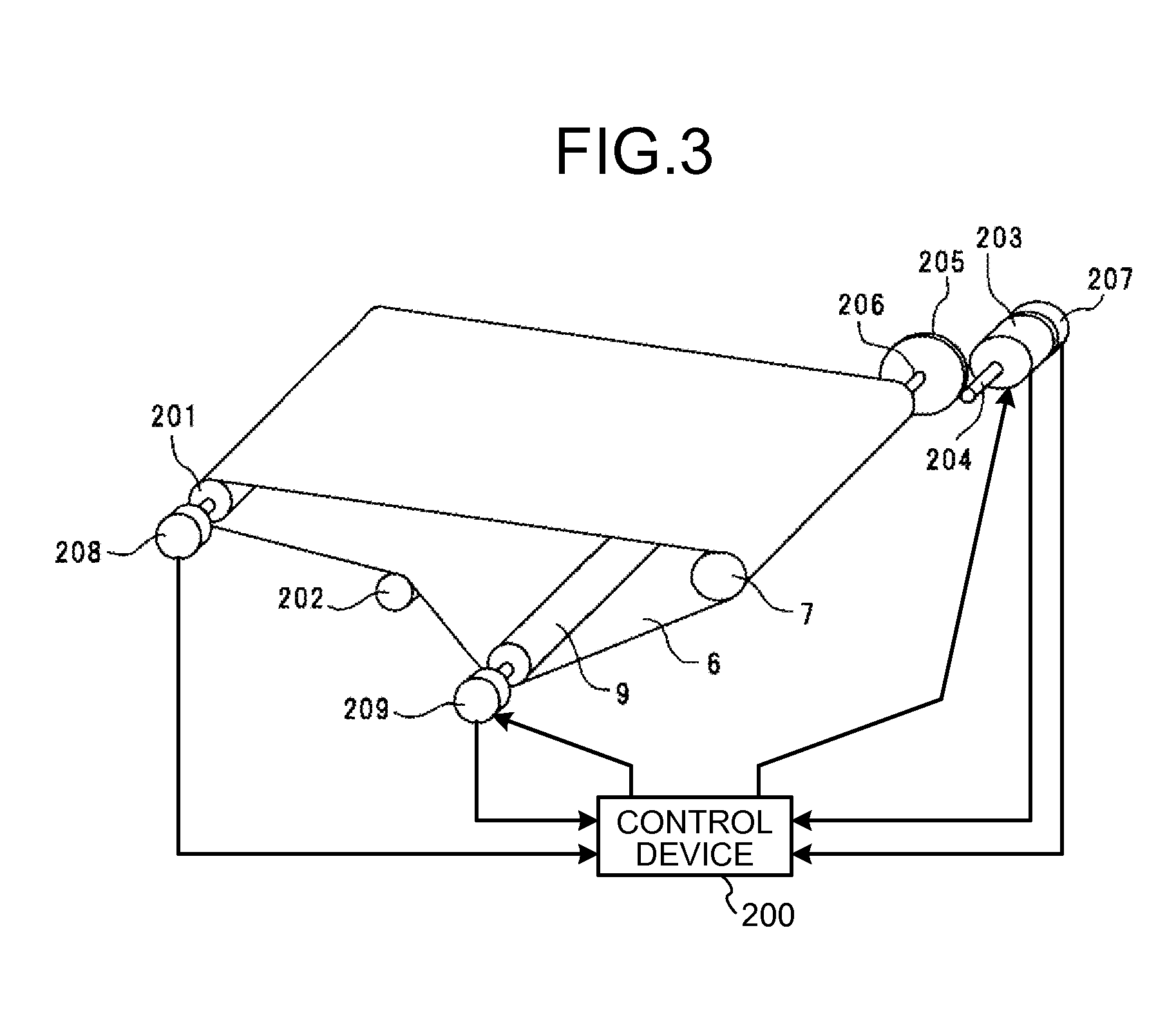
[0101]FIG. 10 is an explanatory diagram of the configuration related to driving control of the intermediate transfer belt 6 according to the second embodiment.

[0102]In the first embodiment, the angular velocity of the driven roller 201 of the intermediate transfer belt 6 is detected when the torque variation occurring on the inertial member, that appears when the intermediate transfer unit portion is regarded as an inertia system, is to be determined. However, in the second embodiment, the torque variation of the inertial ...

third embodiment

[0108]An explanation will be given below of a still another embodiment (hereinafter, referred to as “third embodiment”), in which the present invention is applied to a copying machine, corresponding to the image formation apparatus, as in the first embodiment and the second embodiment.

[0109]The third embodiment is similar to the first embodiment with a difference from the first embodiment only in that the driving force exerted by the auxiliary motor 209 is applied to the intermediate transfer belt 6. Therefore, only the difference will be described below.

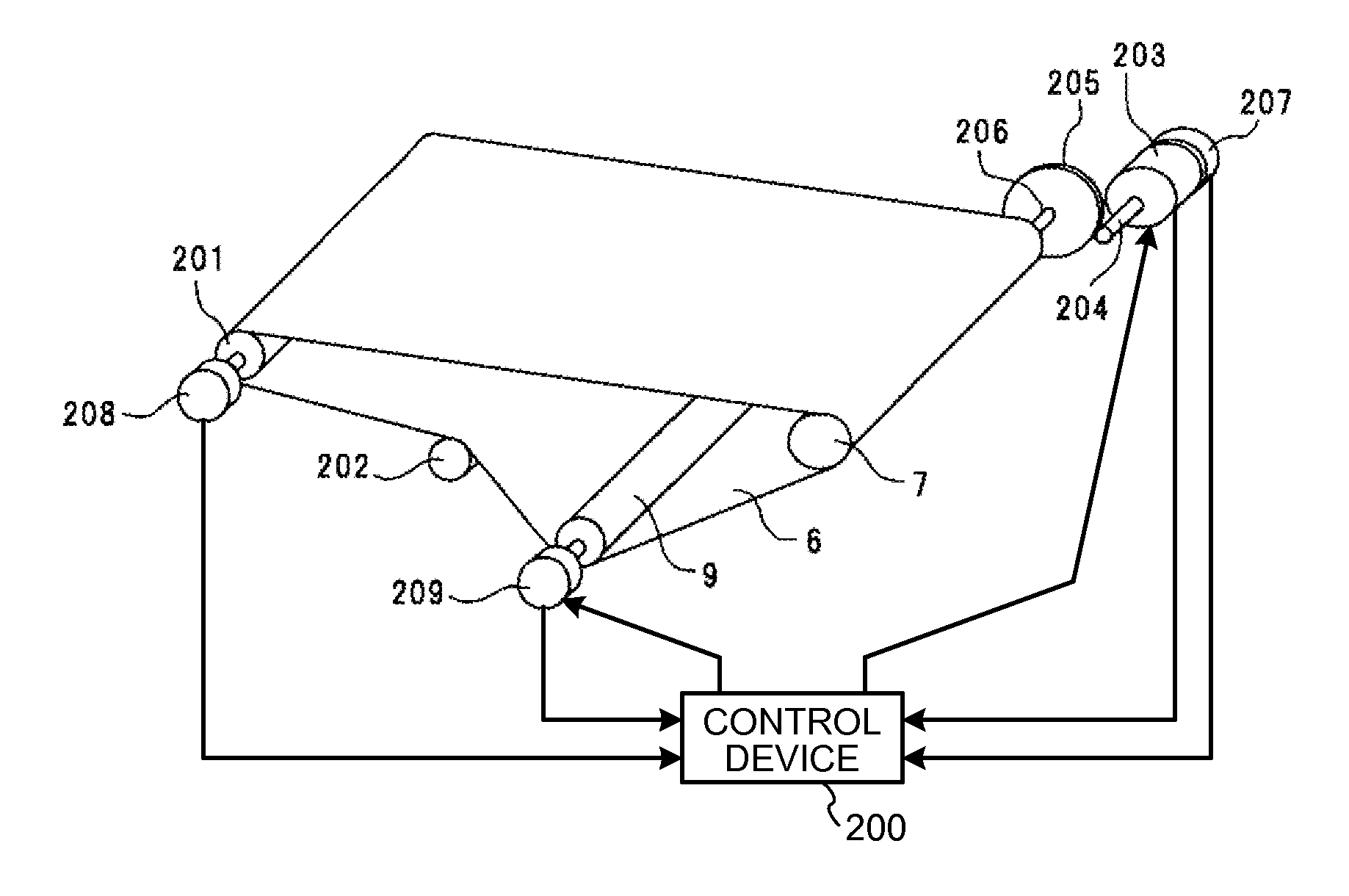
[0110]FIG. 13 is an explanatory diagram of the configuration related to driving control of the intermediate transfer belt 6 according to the third embodiment.

[0111]In the first embodiment, the auxiliary motor 209 is attached via the coupling (not shown) to the rotary shaft of the secondary-transfer opposed roller 9. In contrast, in the third embodiment, the auxiliary motor 209 is attached via a coupling (not shown) to the rotary sha...


PUM


Abstract

An image formation apparatus includes an image carrier; a driving source generating a driving force for the image carrier; a drive transmission unit; a driving control unit controlling the driving source; an image formation unit forming an image on a surface of the image carrier; a transfer nip between a transfer member and the surface of the image carrier; a driving-force exerting unit exerting a driving force on any one of the image carrier and a first drive transmission member on a drive transmission path, and a specific drive transmission member imparting weakest spring characteristics among drive transmission members to a drive transmission system; a detecting unit detecting an estimation parameter used in estimating a driving-load-torque variation amount of the image carrier; a torque-variation-amount estimation unit; and a driving-force control unit controlling the driving force to cancel the driving-load-torque variation.

Description

CROSS-REFERENCE TO RELATED APPLICATIONS[0001]The present application claims priority to and incorporates by reference the entire contents of Japanese Patent Application No. 2010-266095 filed in Japan on Nov. 30, 2010. The present document incorporates by reference the entire contents of Japanese application, 2009-272023 filed in Japan on Nov. 30, 2009.BACKGROUND OF THE INVENTION[0002]1. Field of the Invention[0003]The present invention relates to an image formation apparatus, such as a copying machine, a printer, or a facsimile, that forms an image by electrophotography, electrostatography, iconography, magnetic recording method, or the like as well as to a driving control method for an image carrier and a computer program product that stores therein a computer program for executing the driving control method.[0004]2. Description of the Related Art[0005]As an image formation apparatus of this type, an image formation apparatus having a transfer nip is widely known. In the apparatus,...

Claims


Application Information

Patent Timeline
Patent Type & Authority Applications(United States)
IPC IPC(8): G03G15/16G03G15/01
CPCG03G15/0189G03G15/1615G03G15/5008G03G15/6564G03G15/5054G03G2215/00075G03G2215/00599G03G2215/00156G03G15/0131G03G2215/00059
Inventor ANDOH, TOSHIYUKIHASHIMOTO, TAKASHIHODOSHIMA, TAKASHIKATO, MASAHIKO
Owner RICOH KK
Why Eureka
Try Eureka