Robot and over-current protection device for a robot

a protection device and robot technology, applied in the field of robots, can solve the problems of machine damage, plastic deformation or other fatal damage, and the joint actuators of the robot may be subjected to a tremendously excessive load, and it is difficult to establish a design margin for the entire robot in terms of the coefficient of static friction

Inactive Publication Date: 2005-08-18
SONY CORP
View PDF12 Cites 36 Cited by
  • Summary
  • Abstract
  • Description
  • Claims
  • Application Information

AI Technical Summary

Benefits of technology

[0022] In view of the above-identified circumstances, it is therefore an object of the present invention to provide a robot and an over-current protec

Problems solved by technology

On the other hand, when such a robot falls on the floor or collides with an object on the floor on the intended route of movement, some or all of the joint actuators of the robot may be subjected to a tremendously excessive load.
The machine can be broken, plastically deformed or otherwise fatally damaged by such an excessive load.
However, such conventional torque limiters 130 are accompanied by a problem that the coefficient of static friction between the annular body 131 and the first and second friction plates 132A, 132B shows a large dispersion among individual torque limiters if they are manufactured according to same numerical specifications so that it is difficult to establish a design margin for the entire

Method used


Image

  • Robot and over-current protection device for a robot
  • Robot and over-current protection device for a robot
  • Robot and over-current protection device for a robot

Examples


Embodiment Construction

[0074] Now, the present invention will be described in greater detail by referring to the accompanying drawings that illustrate a preferred embodiment of the invention.

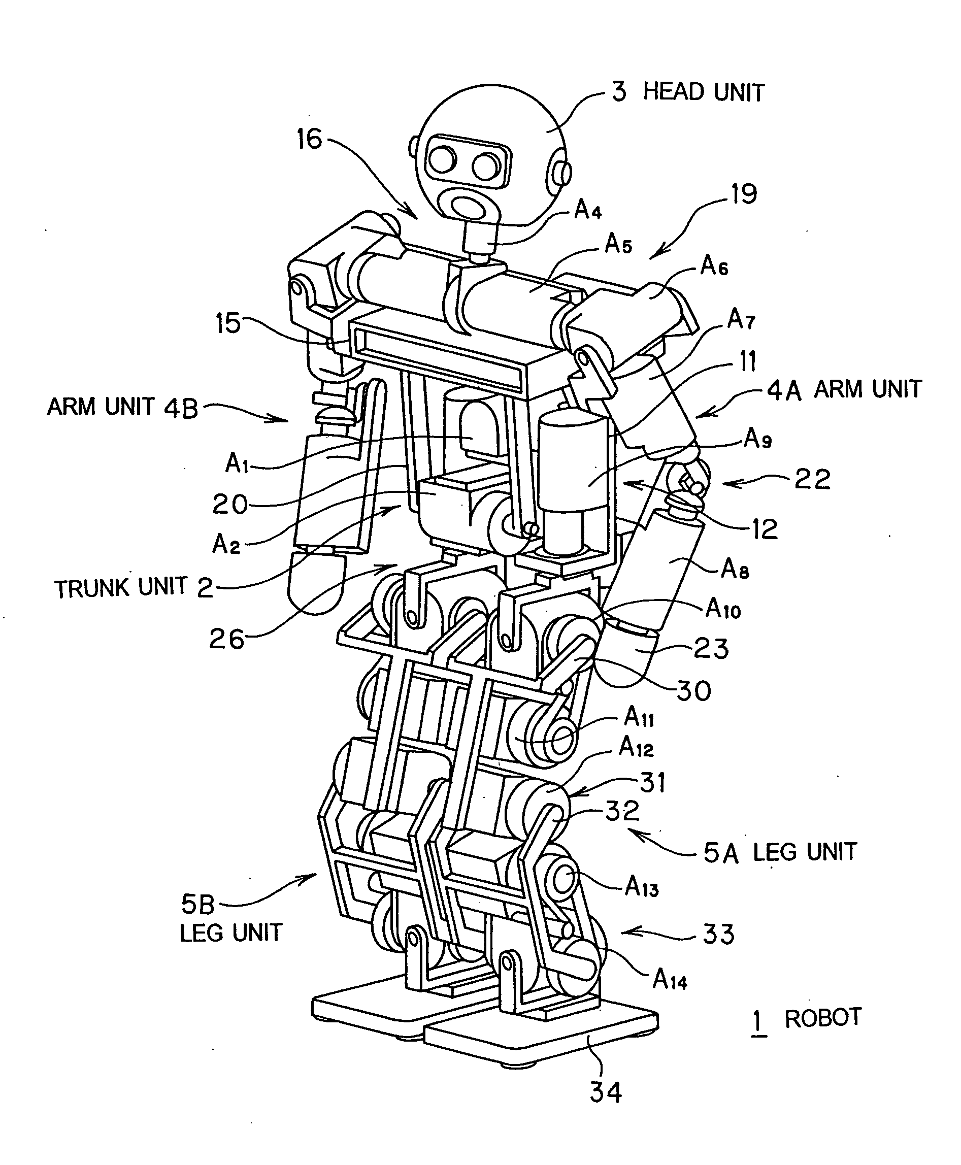
A. Configuration of the Embodiment of Robot

[0075] A legged mobile robot that operates on the principle of erect bipedalism is a structure comprising a base body and four limbs fitted to the base body. The expression of “base body” as used herein refers to a part of the trunk section of the robot that is the object of control and defined near the pelvis link for linking the left and right hip joints or at the trunk where the center of gravity of the entire robot is located or the operable mass is maximal. The operable mass as used herein refers to the mass of the members that can be moved at a same time in the robot. The member where the operable mass is maximal is the movable member of the robot that shows the largest mass (for example, the member showing the largest mass that is not movable is not the member where...


PUM


Abstract

It is so arranged in a robot as to monitor the over-current state of each motor and that of two more than two motors when put together by seeing the total current value of the motors being monitored in parallel with absorption of both the static load torque and the dynamic load torque of each actuator/motor. Additionally, it is so arranged as to check if each of the predetermined unit members including the arm sections and the leg sections of the robot is in an over-current state or not and also if the entire robot is in an over-current state or not, while each of the motors are not in an over-current state.

Description

BACKGROUND OF THE INVENTION [0001] 1. Field of the Invention [0002] This invention relates to a robot comprising a plurality of joint axes, links coupling the joints and actuators for driving the joint axes and adapted to operate by supplying a drive current to the actuators. More particularly, the present invention relates to a robot adapted to prevent an over-current from flowing to any of its actuators during an operation and also to an over-current protection device to be used for such a robot. [0003] Still more particularly, the present invention relates to a robot adapted to prevent an over-current from flowing to any of its actuators when an excessively heavy load is applied to the related joint axes and also to an over-current protection device to be used for such a robot. Still more particularly, the present invention relates to a robot adapted to prevent an over-current from flowing to any of its actuators when a heavy load that exceeds the permissible limit of the entire ...

Claims


Application Information

Patent Timeline
IPC IPC(8): B25J19/06B25J5/00B25J9/16H02P5/46
CPCY10S388/903B25J9/1674
Inventor IRIBE, MASATSUGUMORIDAIRA, TOMOHISAYAMAGUCHI, HIROSHI
Owner SONY CORP
Why Eureka
Try Eureka