Simulated flame structure

a flame structure and flame technology, applied in the field of electronic lighting, can solve the problems of predetermined security risks, and cannot be replaced by the illumination lamps used in the current daily life,

Inactive Publication Date: 2016-12-20
GLOBAL RICH INVESTMENT CO LTD
View PDF10 Cites 5 Cited by
  • Summary
  • Abstract
  • Description
  • Claims
  • Application Information

AI Technical Summary

Benefits of technology

[0008]Another object of the invention is to provide a simulated flame structure to replace the appliance, such as the candle or oil lamp that needs the flame combustion, to decrease the disasters caused by careless use, to avoid the harmful gas generated by the combustion (or incomplete combustion), and thus to enhance the environment quality,
[0012]Preferably, the position limiting hole is further inwardly projectingly formed with at least two position limiting pillars, and a position limiting space is formed between end portions of the position limiting pillars to restrict a swingable range of the simulated flame element.

Problems solved by technology

In today's society, although conventional illumination tools, such as candles, oil lamps or the like, have been replaced by various electric lamps, the candles or the oil lamps still have conventional meanings and distinctive visual effects in some special occasions or special situations, and thus cannot be replaced by the illumination lamps used in the today's daily life.
However, the conventional lamps, such as candles, oil lamps or the like, are used for illumination by way of flame combustion, and have the predetermined security risks.
When the candles or oil lamps are upset due to the wind blowing or the artificial inadvertent touch, the ambient flammable objects tend to be ignited to cause the fire accident.
However, this lamp shade of the simulated lamp has the fixed shape, and the stable light source is formed after lighting and significantly different from the dynamic visual effect of the flame combustion on the candle.

Method used


Image

  • Simulated flame structure
  • Simulated flame structure
  • Simulated flame structure

Examples


Embodiment Construction

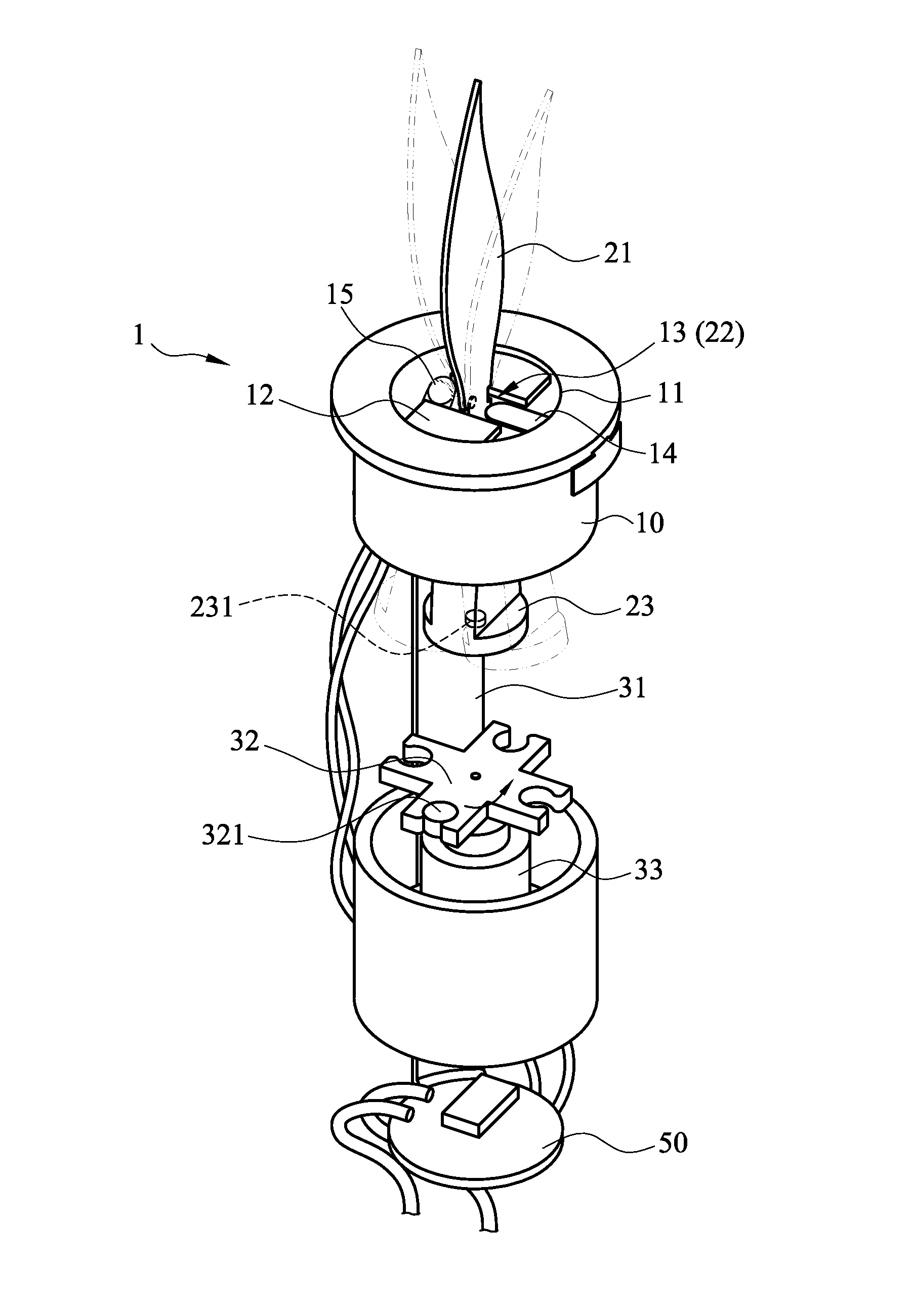
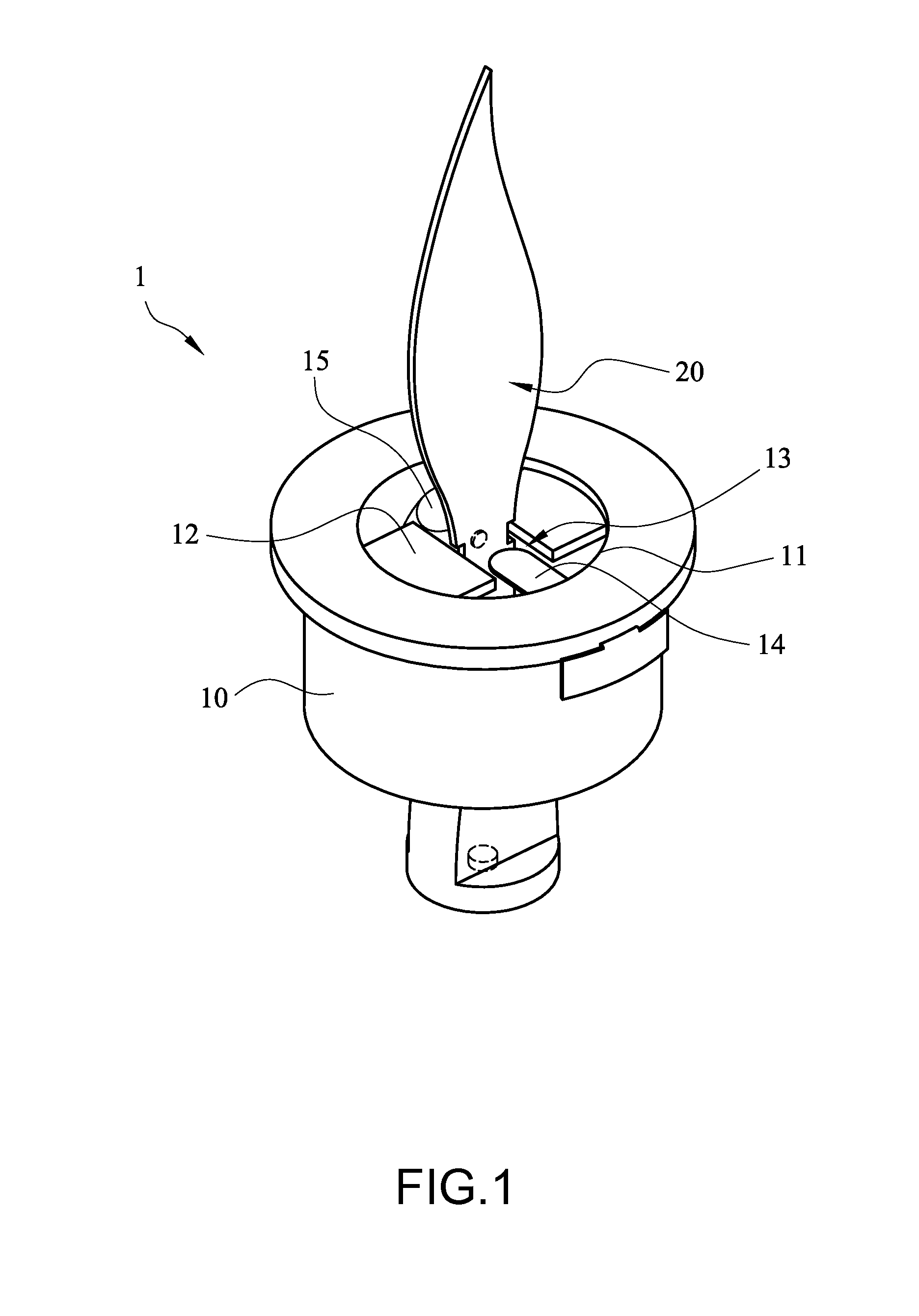
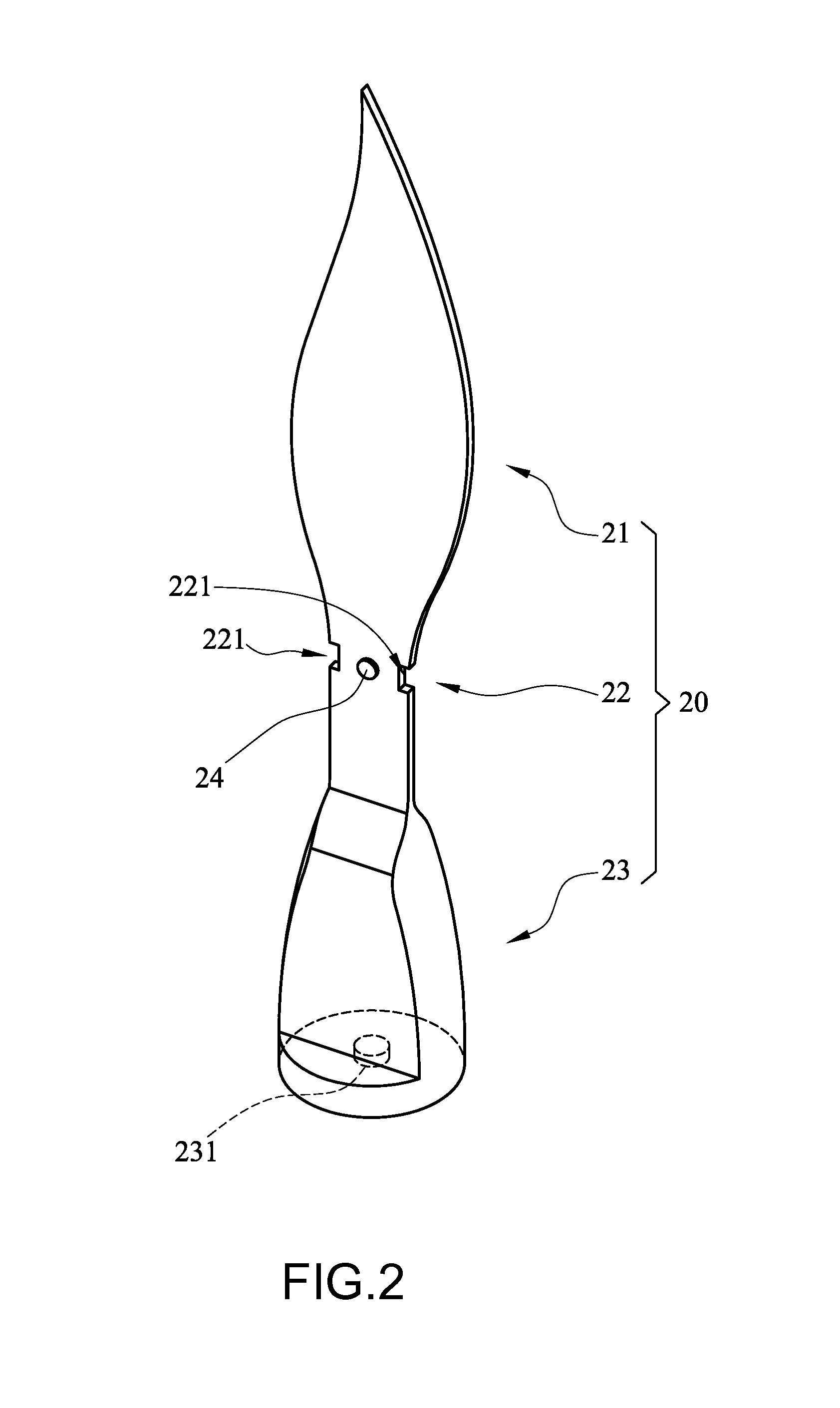
[0028]Referring to FIGS. 1 and 2, a main structure of a simulated flame structure 1 of this embodiment comprises a bracket 10 and a simulated flame element 20. The bracket 10 is formed with a circular position limiting hole 11. Two opposite sides of the position limiting hole 11 are inwardly projectingly formed with two position limiting pillars 12. A position limiting space 13 is formed between the end portions of the two position limiting pillars 12. The simulated flame element 20 includes a flame portion 21, a position limiting portion 22 and a vertical swinging portion 23. The position limiting portion 22 is disposed between the flame portion 21 and the vertical swinging portion 23. The simulated flame element 20 is restricted in the position limiting hole 11 through the position limiting portion 22, so that the simulated flame element 20 can swing relatively to the bracket 10 about the position limiting portion 22 serving as the center. In this embodiment, the position limiting...


PUM


Abstract

A simulated flame structure comprises a bracket, a simulated flame element, a first magnetic element and a light-emitting element. The bracket is formed with a position limiting hole. The simulated flame element is restricted in the position limiting hole through a position limiting portion. The first magnetic element is disposed on the simulated flame element. The light-emitting element is disposed on the bracket and outputs light toward the simulated flame element. By magnetic attractive actions between the first magnetic element and a metal element in the position limiting hole, the simulated flame element may be suspended in the position limiting hole and naturally swing relatively to the bracket, thereby achieving visual effects of optimized flame combustion.

Description

BACKGROUND OF THE INVENTION[0001]1. Field of the Invention[0002]The invention relates to applications of electronic lighting, and more particularly to a simulated flame structure of simulating flame combustion.[0003]2. Description of the Prior Art[0004]In today's society, although conventional illumination tools, such as candles, oil lamps or the like, have been replaced by various electric lamps, the candles or the oil lamps still have conventional meanings and distinctive visual effects in some special occasions or special situations, and thus cannot be replaced by the illumination lamps used in the today's daily life. For example, upon worshiping deities or ancestors, incense and candles are often used, and the beating fire on the candle is used to anchor the reminiscence on the ancestor and the endless longing to the posterity. Alternatively, in some occasions where specific atmospheres need to be created, the fire beating effect of the burning candle is also advantageous to the...

Claims


Application Information

Patent Timeline
Patent Type & Authority Patents(United States)
IPC IPC(8): F21S6/00F21S10/04F21W111/10F21W121/00
CPCF21S10/046F21S6/001F21W2111/10F21W2121/00
Inventor LAI, WEN-CHENG
Owner GLOBAL RICH INVESTMENT CO LTD
Why Eureka
Try Eureka