
Power electronic switching system

a technology of electronic switching and power, applied in the field of power electronics, can solve the problems likely not being able to support an application, and design of power-electronic switching system of wo 2008

Active Publication Date: 2016-12-20
ABB (SCHWEIZ) AG
View PDF26 Cites 0 Cited by
  • Summary
  • Abstract
  • Description
  • Claims
  • Application Information

AI Technical Summary

Benefits of technology

This patent is about a power-electronic switching system that includes multiple switching units. Each unit has a housing with at least one switching module inside. The switch modules are mounted on a mounting unit that includes an insulation material to electrically isolate the switching units from one another. The housing of each switching unit also includes a material to shield the electric and magnetic field. The main technical effect of the patent is to provide a system that efficiently distributes power and can handle high current levels while maintaining insulation between the switching units.

Problems solved by technology

The power-electronic system of WO 2008 / 005485 A2, however, would likely not be capable of supporting an application in which the housings of the switching units are set at different voltage potentials, for example.
Furthermore, the design of the power-electronic switching system of WO 2008 / 005485 A2 is complex and can call for a large space since each switching unit specifies two rails which additionally have to be attached to a frame structure.
Therefore, production specification of a known power-electronic switching system of this type can be complex, call for a large amount of time and experience in respect of mounting, and can therefore be expensive.

Method used


Image

  • Power electronic switching system
  • Power electronic switching system
  • Power electronic switching system

Examples


Embodiment Construction

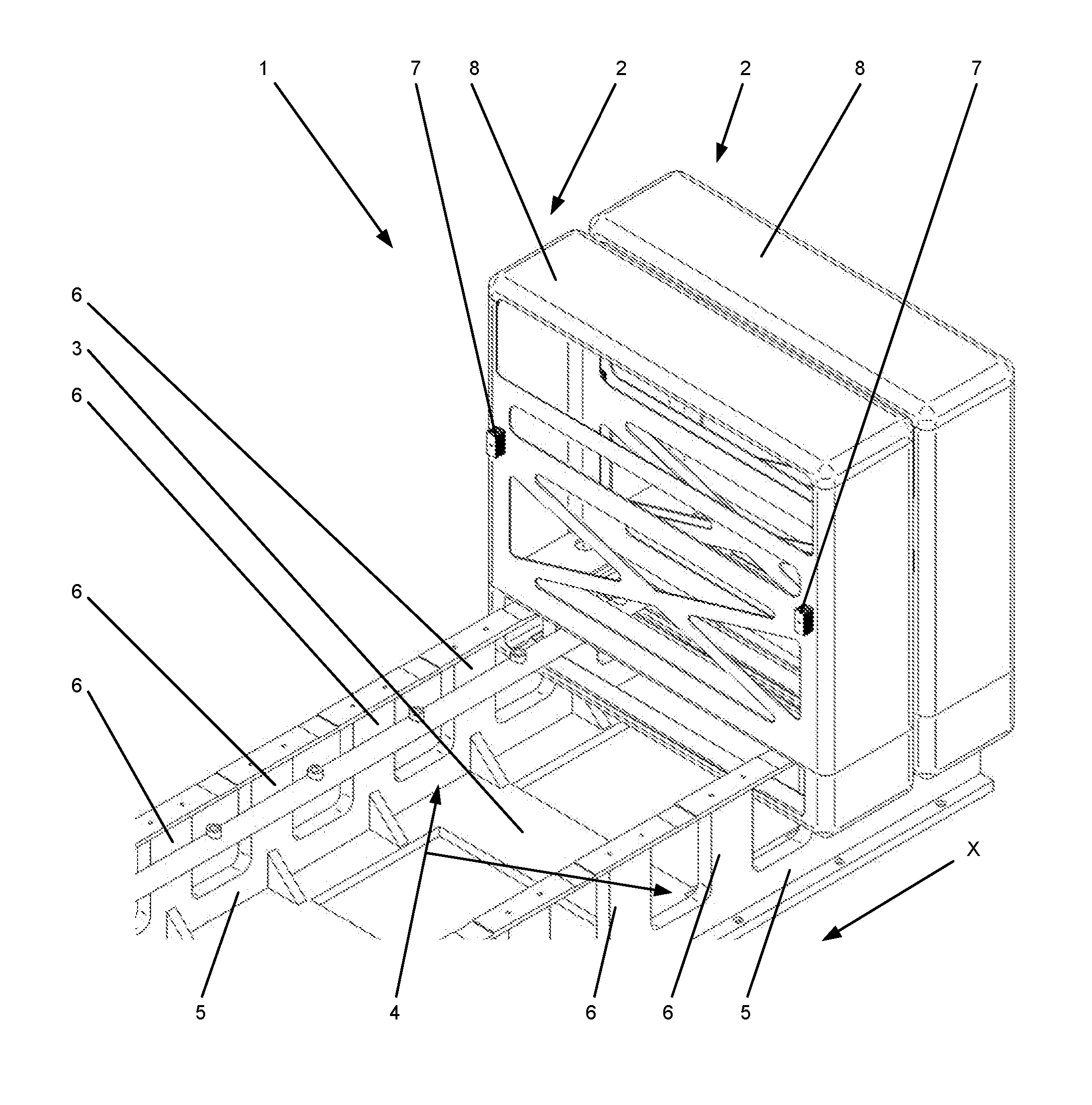
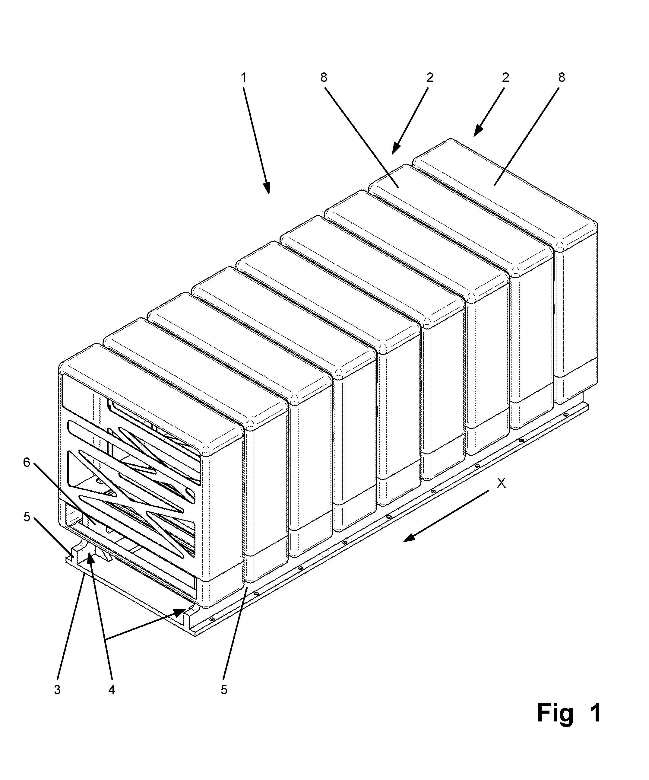
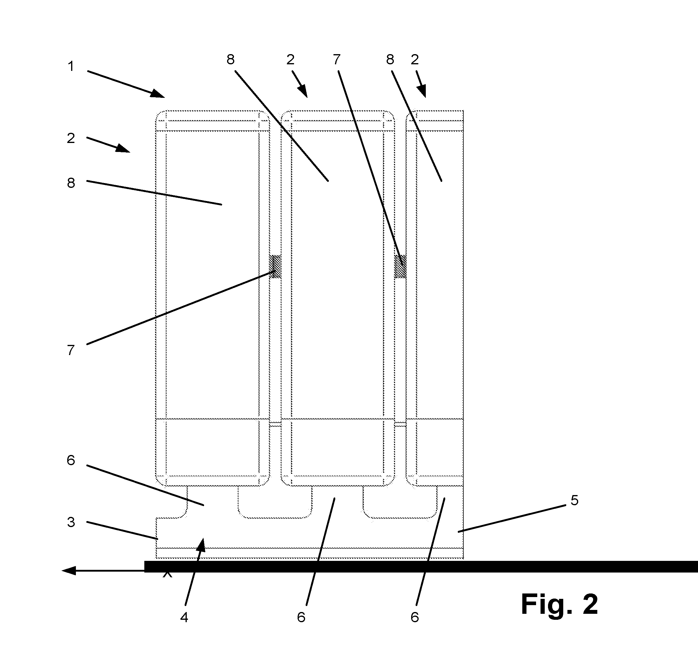
[0015]Exemplary embodiments of the present disclosure specify a power-electronic switching system which allows the housings of the switching units of the switching system to have different voltage potentials from one another and which additionally can be realized in a simple and space-saving manner and can be assembled without problems.

[0016]An exemplary power-electronic switching system according to the present disclosure can include a large number of switching units, wherein each switching unit has a housing and at least one switching module which is arranged within the housing. The power-electronic switching system further includes a mounting unit, wherein the mounting unit has a holding apparatus, on which holding apparatus the housings of the switching units are arranged. According to another exemplary embodiment of the disclosure, the holding apparatus can include an insulation material for electrically insulating the holding apparatus from the housings of the switching units ...


PUM


Abstract

An exemplary power-electronic switching system has a plurality of switching units, wherein each switching unit includes a housing and at least one switching module which is arranged within the housing. A mounting unit has a holding apparatus, on which the housings of the switching units are arranged. The holding apparatus includes an insulation material for electrically insulating the holding apparatus from the housings of the switching units and the housings of the switching units from one another. The insulation material allows the housings of the switching units of the switching system to have different voltage potentials from one another and additionally can be realized in a simple and space-saving manner and easily be assembled. In addition, the housing of each switching unit includes a material for at least partially shielding an electric and magnetic field.

Description

RELATED APPLICATION(S)[0001]This application claims priority as a continuation application under 35 U.S.C. §120 to International Application PCT / EP2012 / 054899, which was filed on Mar. 20, 2012, designating the U.S., and claiming priority to German Application 20 2011 005 290.7 filed in Germany on Apr. 14, 2011 and German Application 20 2011 100 208.3 filed in Germany on May 3, 2011. The content of each prior application is hereby incorporated by reference in its entirety.FIELD[0002]The present disclosure refers to the field of power electronics, and particularly to power-electronic switching system having electrically insulating material.BACKGROUND INFORMATION[0003]Known power-electronic switching systems can be found in converter circuits for an extremely wide variety of applications. A power-electronic switching system of this kind can includes a large number of switching units and a mounting unit, wherein the mounting unit has a holding apparatus on which the housings of the swit...

Claims


Application Information

Patent Timeline
Patent Type & Authority Patents(United States)
IPC IPC(8): H05K7/14
CPCH05K7/1411H05K7/1432H05K7/1457H05K7/1471H05K7/1474H05K7/14324
Inventor WEISS, MICHAELLUSCHER, ROGERIORDANIDIS, ARTHOUROSCRANGANU-CRETU, BOGDANSTEINKE, JURGEN
Owner ABB (SCHWEIZ) AG
Learn More