Method of grouping transmitter-receiver pairs for communicating over a communications network

a communication network and transmitter-receiver technology, applied in the field of communication, can solve the problems of affecting the transmission speed of the transmission network, unable to ensure the transmission network performance, and unable to take into account so as to achieve the effect of improving the total spectrum efficiency of the system, maximizing the system spectrum efficiency, and improving the estimation of these directions

Active Publication Date: 2016-12-27
ORANGE SA (FR)
View PDF49 Cites 0 Cited by
  • Summary
  • Abstract
  • Description
  • Claims
  • Application Information

AI Technical Summary

Benefits of technology

[0033]By selecting the group that optimizes a global metric calculated on the basis of metrics associated with the various transmitter-receiver pairs of the group, the selected group is the group that is the most promising from the point of view of distance between the vector subspace generated by the useful signal and the vector subspace generated by the interferences, in other words it is the group that maximizes the spectrum efficiency of the system. The invention thus also improves the total spectrum efficiency of the system. This improvement is associated not only with the criterion taken into consideration for selecting the group, but also with the fact that this criterion relies on a metric evaluated after executing the interference alignment technique for a predetermined number I1 of iterations (I1 greater than or equal to 1).
[0034]Executing the interference alignment technique in each group under test, even over a number I1 of iterations that is relatively limited, makes it possible to identify approximately the directions of the interferences and the direction of the useful signal. The estimate of these directions is subsequently improved by processing the precoded pilot signals transmitted successively by the NG transmitters of the group. In accordance with the invention, when any one transmitter of the group transmits a pilot signal, the other transmitters of the group are inactive (i.e. they remain silent), such that it is much easier for the receivers of the group to estimate the directions of the useful signal and of the interferences.
[0038]During this execution of the alignment technique, the pairs of the selected group can advantageously reuse as initial values the precoding matrices and the interference suppression matrices as evaluated during the preceding I1 iterations executed by the group. This obtains faster convergence for the interference alignment technique (in other words, I2 is smaller).

Problems solved by technology

In known manner, a major problem encountered in networks in which a plurality of transmitter-receiver pairs may be communicating simultaneously lies in the interference these transmitter-receiver pairs generate between one another.
Nevertheless, it will readily be understood that even though opting for grouping in this way does not add complexity to the system, it does not enable system performance to be guaranteed, in particular in terms of data rate.
Nevertheless, although such a method does indeed make it possible to improve the data rate that is achieved by the system, it does not take account of the total spectrum efficiency of the system.
It may also present a large amount of complexity when the exhaustive search stage II is performed, in particular because of repeated execution of the interference alignment technique and because of the information required for such execution (e.g. global knowledge of the propagation channel at each transmitter).
Such complexity increases even further when consideration is given to an iterative interference alignment technique, since that generally requires a large number of iterations in order to converge.

Method used


Image

  • Method of grouping transmitter-receiver pairs for communicating over a communications network
  • Method of grouping transmitter-receiver pairs for communicating over a communications network
  • Method of grouping transmitter-receiver pairs for communicating over a communications network

Examples


Embodiment Construction

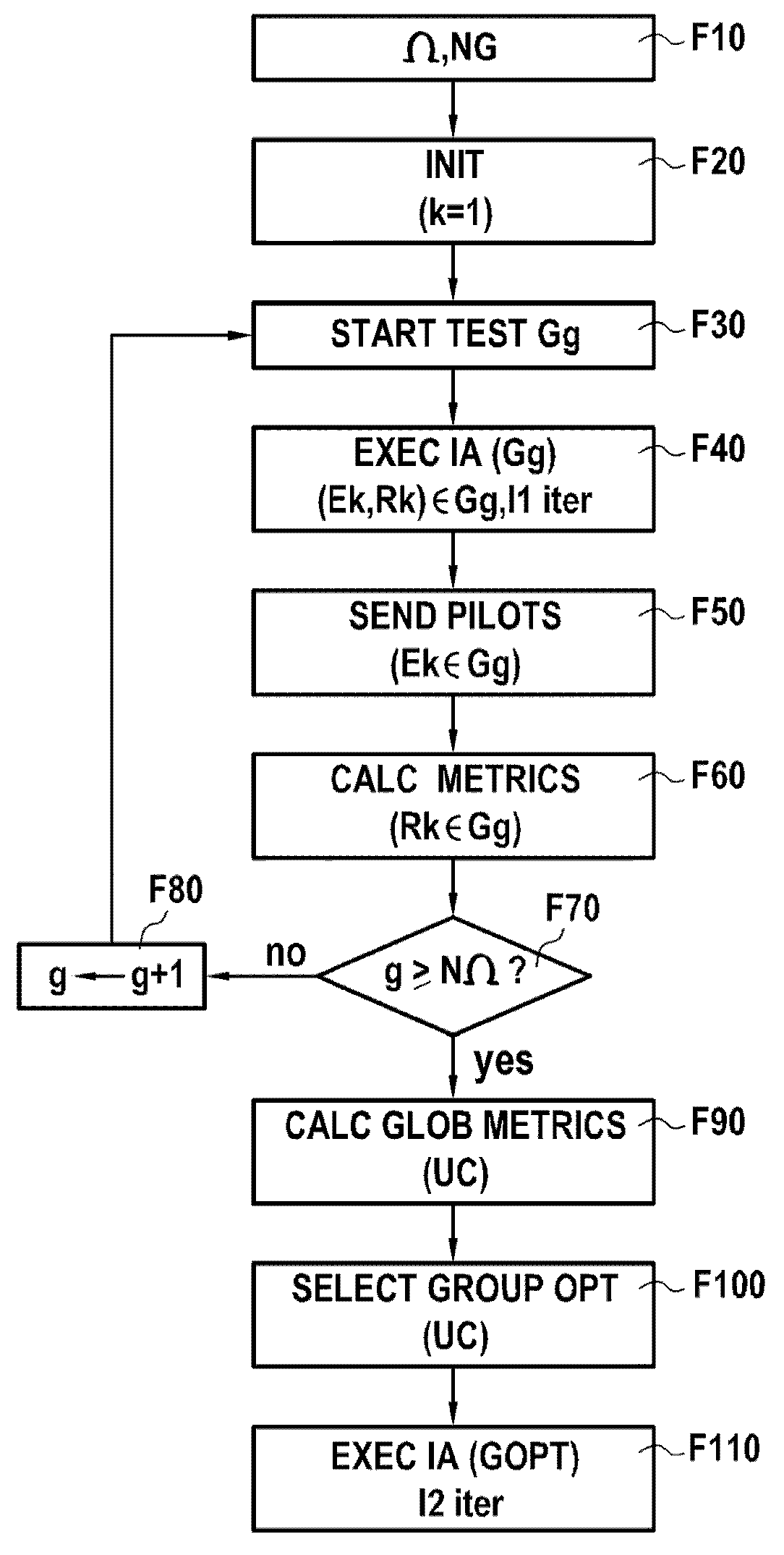
[0091]FIG. 2 shows a communications network NW system 1 in accordance with a particular embodiment of the invention in its environment.

[0092]In accordance with the invention, the system 1 comprises:[0093]a plurality of transmitters E1, E2, . . . , EJ in accordance with the invention;[0094]a plurality of receivers R1, R2, . . . , RN in accordance with the invention; and[0095]a central unit UC in accordance with the invention.

[0096]In this example, each transmitter is fitted with MT transmit antennas, where MT>1, and each receiver is fitted with MR receive antennas, where MR>1.

[0097]In the presently-described example, the network NW is a WiFi® network: the transmitters E1, E2, . . . , EJ are access points to the network NW and the receivers R1, R2, . . . , RN are terminals of users seeking to access the network NW.

[0098]Naturally, the invention applies in other contexts, and in particular to other communications networks and to other transmitter and / or receiver devices. Thus, by way o...


PUM


Abstract

Disclosed is a method of grouping transmitter-receiver pairs for communicating over a communications network. For each group of a set of groups of transmitter-receiver pairs, the pairs of the group execute an iterative interference alignment technique for I1 iterations on signals transmitted by the group. Each transmitter of the group successively sends a pilot signal that has been precoded by a matrix resulting from that execution. Each receiver of the group evaluates a metric representative of a distance between a vector subspace generated by the pilot signal transmitted by the transmitter with which it forms a pair and a vector subspace generated by interferences determined from the pilot signals transmitted by the other transmitters. A central unit calculates a global metric associated for each group on the basis of the metrics from the receivers of the group and selects from the set a group that optimizes the global metric.

Description

RELATED APPLICATIONS[0001]This application is the U.S. National Phase of Application No. PCT / FR2012 / 052996 entitled “METHOD FOR FORMING GROUPS OF TRANSMITTER / RECEIVER PAIRS FOR COMMUNICATING OVER A COMMUNICATION NETWORK” filed Dec. 19, 2012, which designated the United States, and which claims the benefit of French Application No. 1162396 Dec. 23, 2011.BACKGROUND OF THE INVENTION[0002]The invention relates to the general field of communications.[0003]The invention relates more particularly to a method of designating a group of transmitter-receiver pairs authorized to communicate simultaneously over a telecommunications network when interference alignment techniques are implemented on the network in order to manage the multiuser interference that is generated by such simultaneous communications. Such a method is also known as a clustering (or grouping) method.[0004]A preferred but non-limiting application of the invention lies in the field of wireless networks, such as for example wi...

Claims


Application Information

Patent Timeline
Patent Type & Authority Patents(United States)
IPC IPC(8): H04B7/04H04W72/08H04W72/12
CPCH04B7/046H04W72/121H04W72/082H04W72/12H04W72/541
Inventor SAADANI, AHMEDBEN HALIMA, SLIM
Owner ORANGE SA (FR)
Why Eureka
Try Eureka