Dental suction tubing

a technology of suction tubing and denta, which is applied in the direction of machine/engine, pump control, saliva remover, etc., can solve the problems of suction stopping, cumbersome use of three instruments, and inability to use all three together

Active Publication Date: 2017-01-03
RONTO DAVID R
View PDF25 Cites 9 Cited by
  • Summary
  • Abstract
  • Description
  • Claims
  • Application Information

AI Technical Summary

Problems solved by technology

However, the use of all three of these instruments together is typically not feasible and even when it is, the use of three instruments is very cumbersome.
In addition, when a currently commercially available high speed suction tube is used, which has a vent hole only in the front, if it is covered by the tongue or cheek, the suction stops and thus it is rendered ineffective.
The current suction devices also provide too strong of suction for a patient to expel saliva into them such that the high speed suction tube must be removed from the mouth and a slow speed saliva ejector inserted to remove excess saliva.
This procedure is not only inefficient, but the slow speed saliva ejector does not allow for movement of the patient's tongue or cheeks because it is highly flexible.

Method used


Image

  • Dental suction tubing
  • Dental suction tubing
  • Dental suction tubing

Examples


Embodiment Construction

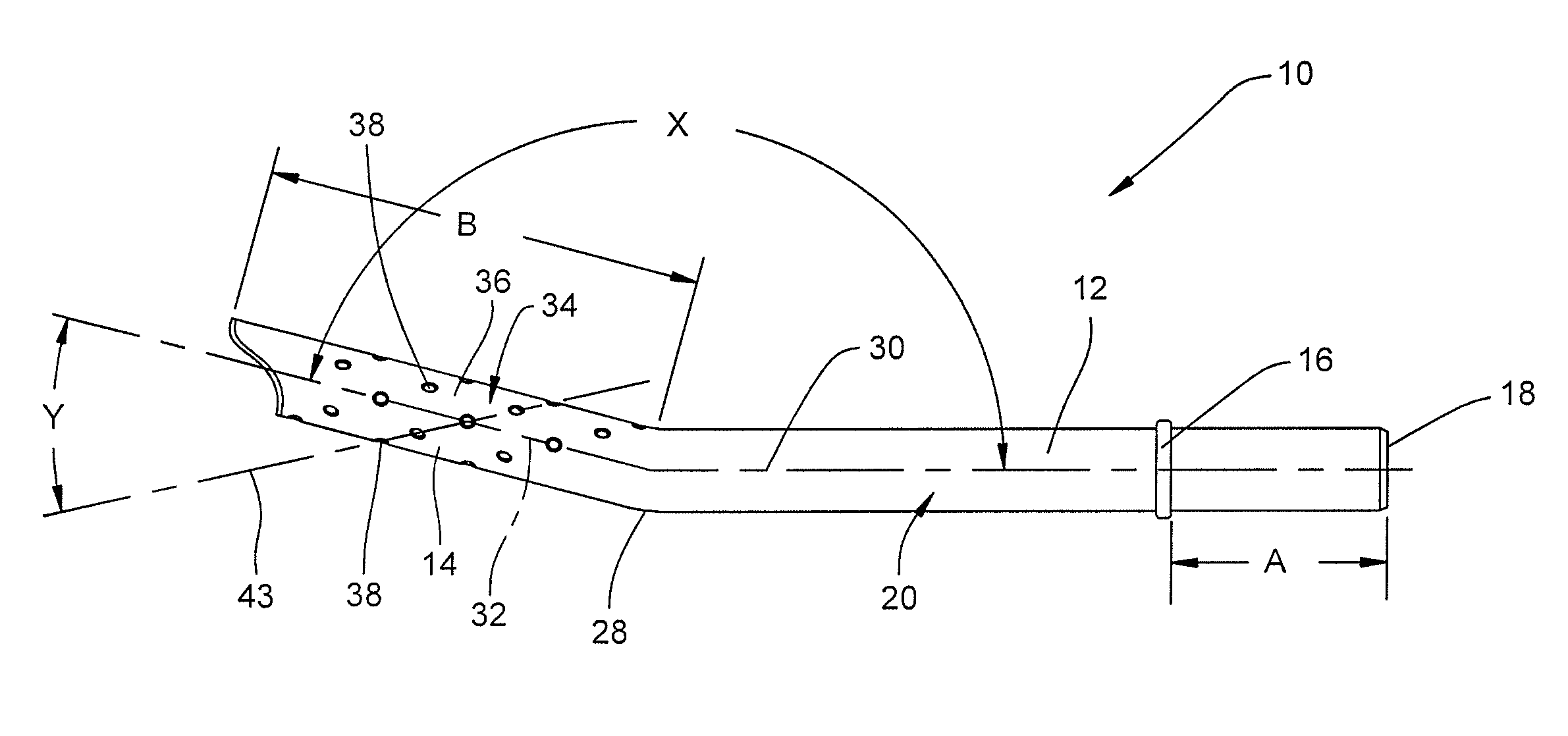
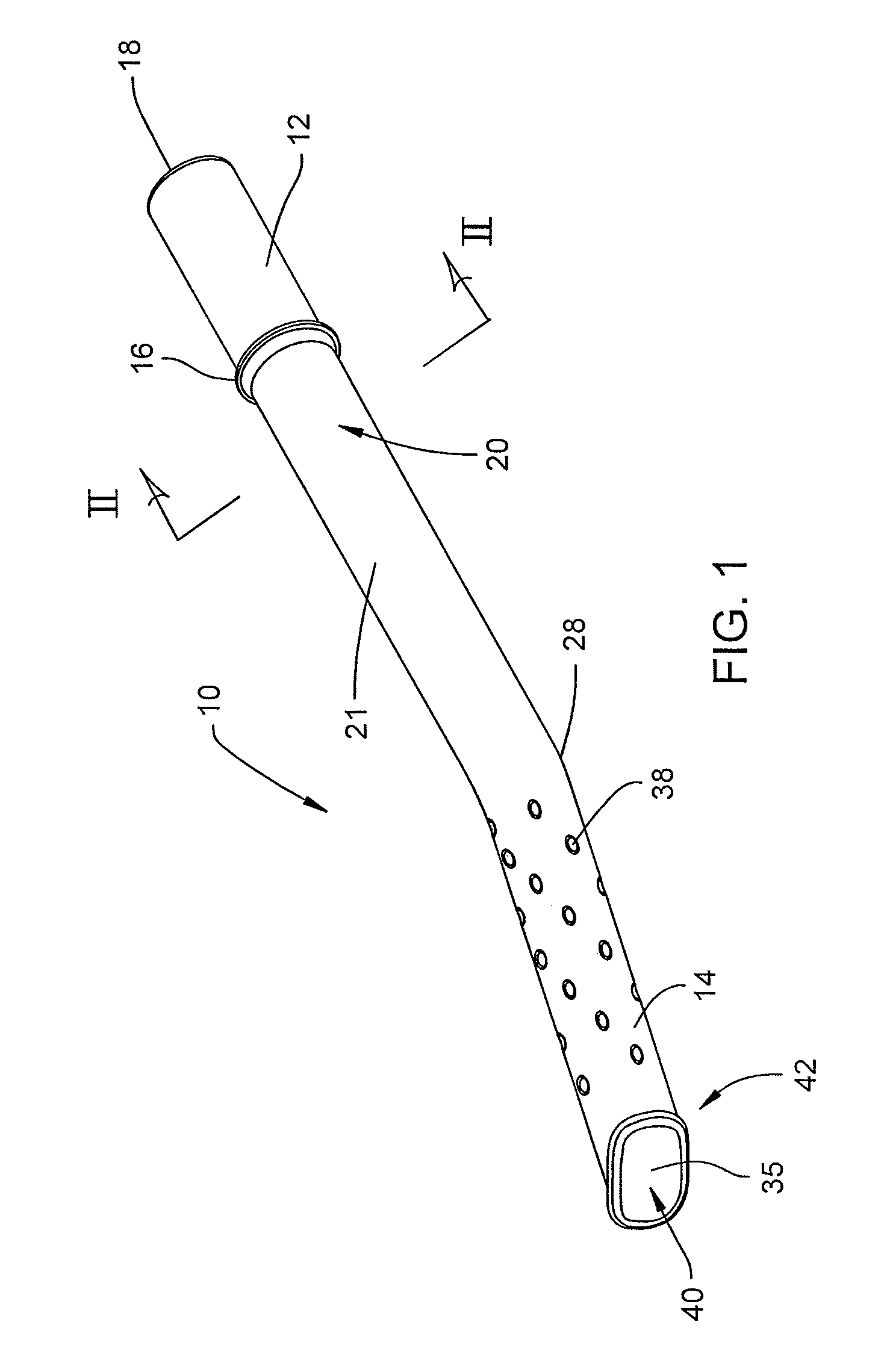
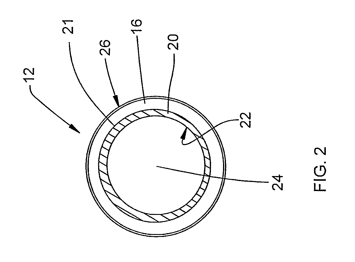
[0015]An embodiment of a dental suction tube 10 of the present invention as shown in FIGS. 1-4. Referring specifically to FIGS. 1 and 2, the dental suction tube 10 includes a proximal portion 12, a distal portion 14, and a stop 16. The proximal portion 12 is preferably cylindrical in shape and substantially tubular in nature. The proximal portion 12 includes a proximal end 18 with an opening and an outer wall 20 having an outer surface 21 and an inner surface 22 (see FIG. 2). The proximal portion 12, and the entirety of the dental suction tube, has a substantially hollow interior 24 which allows conveyance of fluids and solids therethrough when suction is applied to the tube 10.

[0016]The stop 16 extends radially outwardly from the outer surface 21 of the proximal portion 12. The stop 16 has a generally flat surface on both its proximal side and distal side. The stop 16 preferably has a rounded or beveled outer edge 26. The stop 16 is preferably distanced from the proximal end 18 a s...


PUM


Abstract

A dental suction tube having a plurality of apertures in a distal portion of the tube is provided. The apertures are provided in a pattern to allow suction performance even when a portion of the distal end of the tube is abutting a portion of the mouth or other item during a dental procedure.

Description

BACKGROUND OF THE INVENTION[0001]The present invention generally relates to dental suction tubing, and more particularly to apparatus for the suction of fluids and solids from the mouth of a dental patient during a procedure.[0002]In dentistry, it is very important to keep the field of view and work area of the mouth dry from water, saliva, and other materials. It is also important to keep the tongue and cheeks of the patient away from the work area.[0003]These objectives have traditionally been accomplished by a combination of different things. A dental mirror can be used to hold the tongue, cheeks, and other structures out of the way. An air-water syringe may also be used to blow air and water into the mouth and onto the dental mirror to keep the mouth and dental mirror clean. The air-water syringe is a small metal tube that is fixed to a controller, and is rigid enough that it may hold the tongue, cheeks, or other structures out of the way, at least temporarily. Further, a dental...

Claims


Application Information

Patent Timeline
Patent Type & Authority Patents(United States)
IPC IPC(8): A61C17/06
CPCA61C17/043F04C2270/0421A61C17/08
Inventor RONTO, DAVID R.
Owner RONTO DAVID R
Why Eureka
Try Eureka