
Bag in box packaging having an inserted panel for receiving a spout of the bag

a bag and box technology, applied in the direction of rigid containers, transportation and packaging, pliable tubular containers, etc., can solve the problems of difficult, if not impossible use, and difficulty in locating the tap in an orientation which is difficult to reach

Inactive Publication Date: 2017-01-03
SCHOLLE IPN CORP
View PDF50 Cites 25 Cited by
  • Summary
  • Abstract
  • Description
  • Claims
  • Application Information

AI Technical Summary

Benefits of technology

The patent describes a bag in box packaging that includes a flexible bag and an outer carton. The flexible bag has a spout and the outer carton has a front wall and two sidewalls. The inner spout retaining member includes a panel that extends between the sidewalls and is positioned between the front wall and the spout. The spout locking member is a hinged panel that captures the spout between the panel and a front flap. The outer carton has a frangible portion that can be removed to access the spout. The spout locking member can be a spout foot or a polymer member that engages with the spout to keep it in place. The outer carton can be positioned on an outside surface with the bottom wall structure in abutment therewith and the spout being positioned proximate a location where the front wall and the bottom wall structure meet. The technical effect of this patent is to provide a secure and easy-to-use packaging solution for flexible bags and outer cartons.

Problems solved by technology

Problematically, for some users it is difficult to couple the tap to the outer box.
Thus, the tap becomes difficult, if not impossible to use.
In addition, due to the manner in which the tap and bag are inserted into the outer box, there are many instances where the tap lies in an orientation which is difficult to reach.
Furthermore, inasmuch as the opening in the box is typically used to secure the tap to the outer box, the opening is often too small to allow for a user to delve deeply into the outer box.

Method used


Image

  • Bag in box packaging having an inserted panel for receiving a spout of the bag
  • Bag in box packaging having an inserted panel for receiving a spout of the bag
  • Bag in box packaging having an inserted panel for receiving a spout of the bag

Examples


Embodiment Construction

[0047]While this invention is susceptible of embodiment in many different forms, there is shown in the drawings and described herein in detail a specific embodiment with the understanding that the present disclosure is to be considered as an exemplification and is not intended to be limited to the embodiment illustrated.

[0048]It will be understood that like or analogous elements and / or components, referred to herein, may be identified throughout the drawings by like reference characters. In addition, it will be understood that the drawings are merely schematic representations of the invention, and some of the components may have been distorted from actual scale for purposes of pictorial clarity.

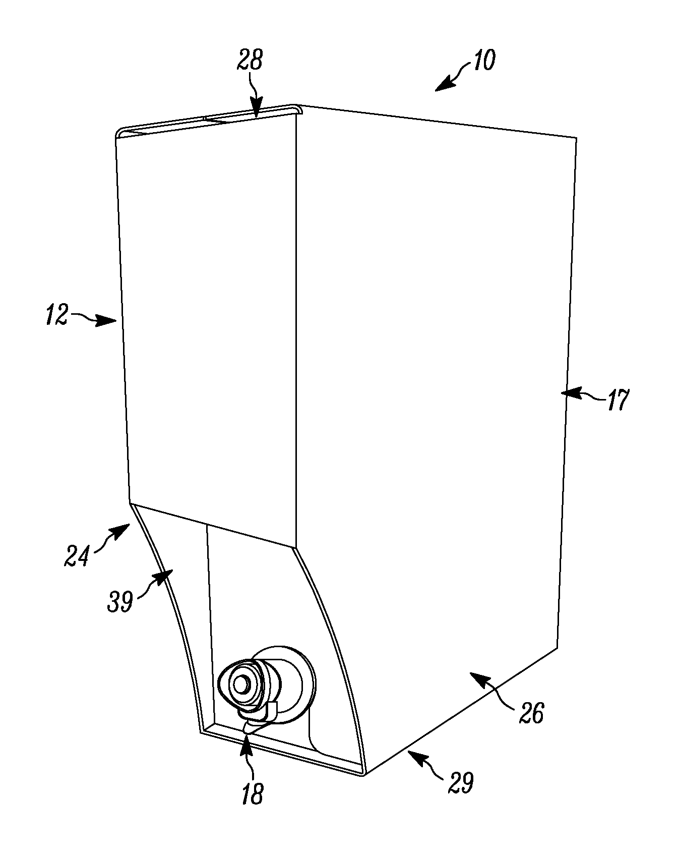
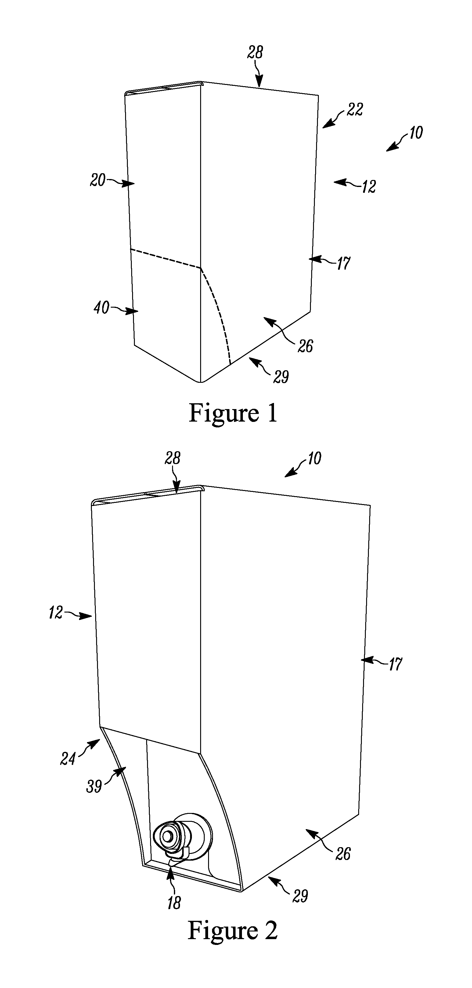
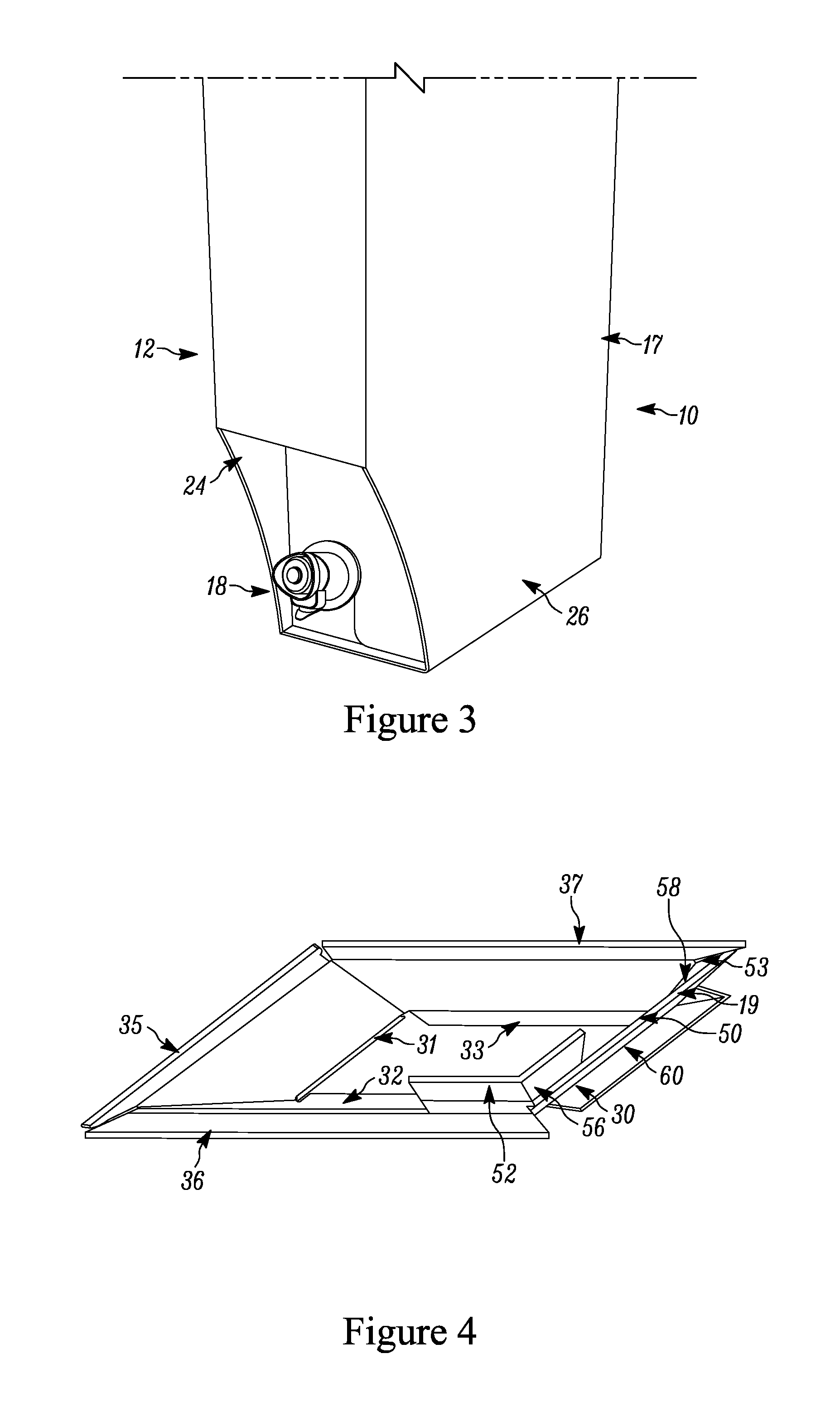
[0049]Referring now to the drawings and in particular to FIGS. 1 through 3, bag in box packaging 10 is shown in FIG. 1 as comprising outer carton 12, inner bag 16 (FIG. 17), and tap 18. The outer carton 12 is shown as comprising outer walls 17 and inner spout retaining member 19. Generally, t...


PUM


Abstract

A bag in box packaging including a flexible bag and an outer carton. The flexible bag defines a cavity, with a spout coupled thereto providing access to the cavity. The outer carton has a first sidewall and a second sidewall opposite the first side wall. A front wall extends therebetween. The inner spout retaining member further includes an inner spout retaining member. The inner spout retaining member includes a first panel that extends between the first sidewall and the second sidewall and is spaced apart from the front wall. The first panel includes a spout receiving slot extending thereinto. The spout of the bag is positionable within the spout receiving slot of the first panel, so as to position the spout between the first panel and the front wall. A spout locking member is structurally configured to maintain the spout within the spout receiving slot of the first panel.

Description

CROSS-REFERENCE TO RELATED APPLICATION[0001]This application claims priority from U.S. Provisional Application Ser. No. 61 / 864,141 entitled “Bag in Box Packaging Having An Inserted Panel For Receiving A Spout Of The Bag,” filed Aug. 9, 2014, the entire specification of which is hereby incorporated by reference.BACKGROUND OF THE DISCLOSURE[0002]1. Field of the Disclosure[0003]The disclosure relates in general to bag in box packaging, and more particularly, to a bag in box packaging that has an inserted panel for receiving a spout of the bag.[0004]2. Background Art[0005]The use of bag in box packaging is ubiquitous. In certain applications, a user can dispense flowable material through a tap directly from the bag in box packaging. One such application is wine dispensing, although, the invention is not limited to the same.[0006]Conventionally, a bag having a fluid therewithin (such as, for example, wine) is provided. A tap is provided over a spout that is welded to the bag. The tap may...

Claims


Application Information

Patent Timeline
Patent Type & Authority Patents(United States)
IPC IPC(8): B65D35/56B65D77/06B67D3/04
CPCB65D77/067B67D3/04
Inventor BROOKS, JOHN
Owner SCHOLLE IPN CORP
Learn More