Laboratory centrifuge with locking system for locking in translation of rotor on driving motor shaft
a technology of locking system and centrifuge, which is applied in the direction of centrifuge, etc., can solve the problems of generating aerodynamic noise, not easy to press on the lug, and not much ergonomics,
- Summary
- Abstract
- Description
- Claims
- Application Information
AI Technical Summary
Benefits of technology
Problems solved by technology
Method used
Image
Examples
Embodiment Construction
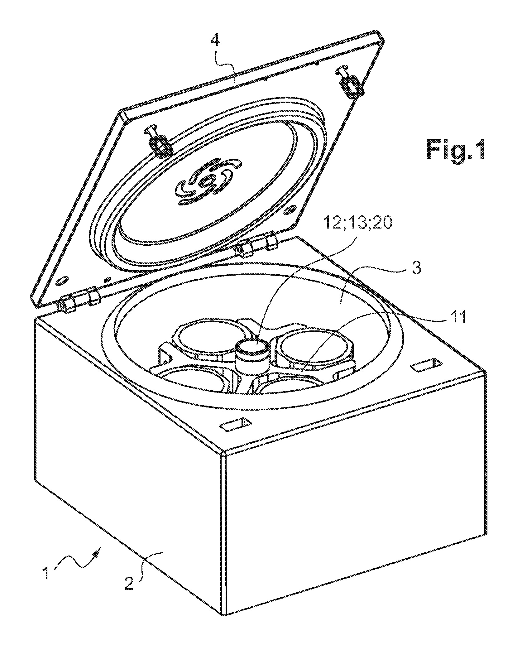
[0057]The laboratory centrifuge 1, as shown in a general and perspective view in FIG. 1, comprises a casing 2 that integrates a shielded bowl 3 and that carries a lid 4.
[0058]This lid 4 is pivotally mounted between—a closed position (not shown), to close the shielded bowl 3, and—an open position (FIG. 1) to clear the access to this bowl 3.
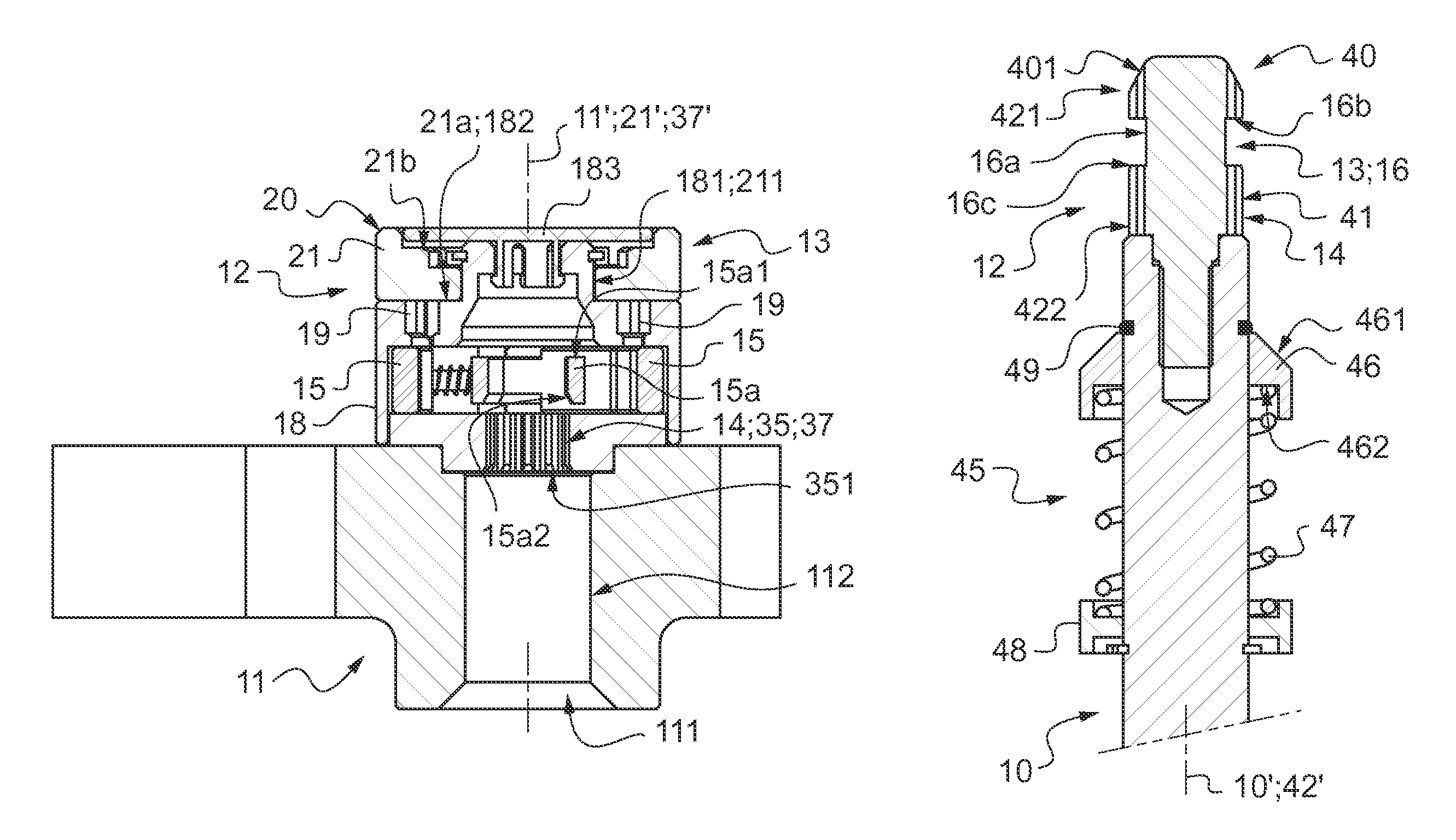
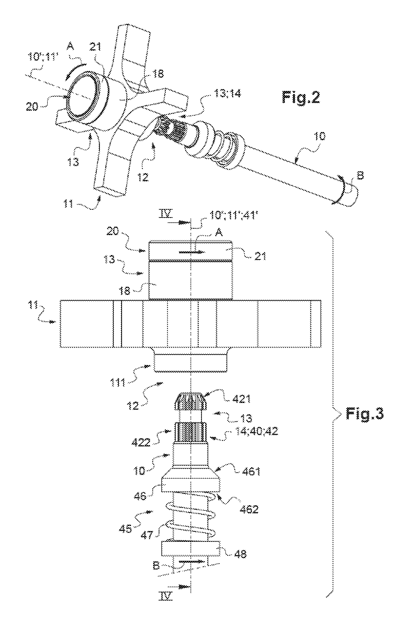
[0059]The shielded bowl 3 contains two rotating parts, which are shown in details in FIGS. 2 to 14, i.e.:[0060]a driving motor shaft 10, rotationally operated by motor means (not shown) integrated in the casing 2, and[0061]a rotor 11, intended to be carried by the driving motor shaft 10.
[0062]The two rotating parts 10, 11 each have a central longitudinal axis 10′, 11′.
[0063]In FIGS. 2 to 14, only the central portion of the rotor 11 is shown.
[0064]Conventionally, the rotor 11 is intended to carry containers (tubes, pockets, etc.) each receiving at least one liquid sample intended to undergo the centrifugation operations.
[0065]The rotor 11 is herein ...
PUM
 Abstract
Description
Claims
Application Information
 - R&D
- Intellectual Property
- Life Sciences
- Materials
- Tech Scout
- Unparalleled Data Quality
- Higher Quality Content
- 60% Fewer Hallucinations
Browse by: Latest US Patents, China's latest patents, Technical Efficacy Thesaurus, Application Domain, Technology Topic, Popular Technical Reports.
© 2025 PatSnap. All rights reserved.Legal|Privacy policy|Modern Slavery Act Transparency Statement|Sitemap|About US| Contact US: help@patsnap.com


