Filler insertion in circuit layout

a circuit layout and filler technology, applied in the field of filler insertion in circuit layout, can solve the problems of inability to meet the needs of a single type of filler

Active Publication Date: 2017-01-10
TEXAS INSTR INC
View PDF4 Cites 73 Cited by
  • Summary
  • Abstract
  • Description
  • Claims
  • Application Information

AI Technical Summary

Problems solved by technology

This leads to certain difficulties like engineering change order (ECO) capability and are not very efficient with power supply robustness.
The ECO is not possible with single type of fillers because the base layers are also required to be changed.
In a metal ECO change the base layers is not ideal.

Method used


Image

  • Filler insertion in circuit layout
  • Filler insertion in circuit layout
  • Filler insertion in circuit layout

Examples


Embodiment Construction

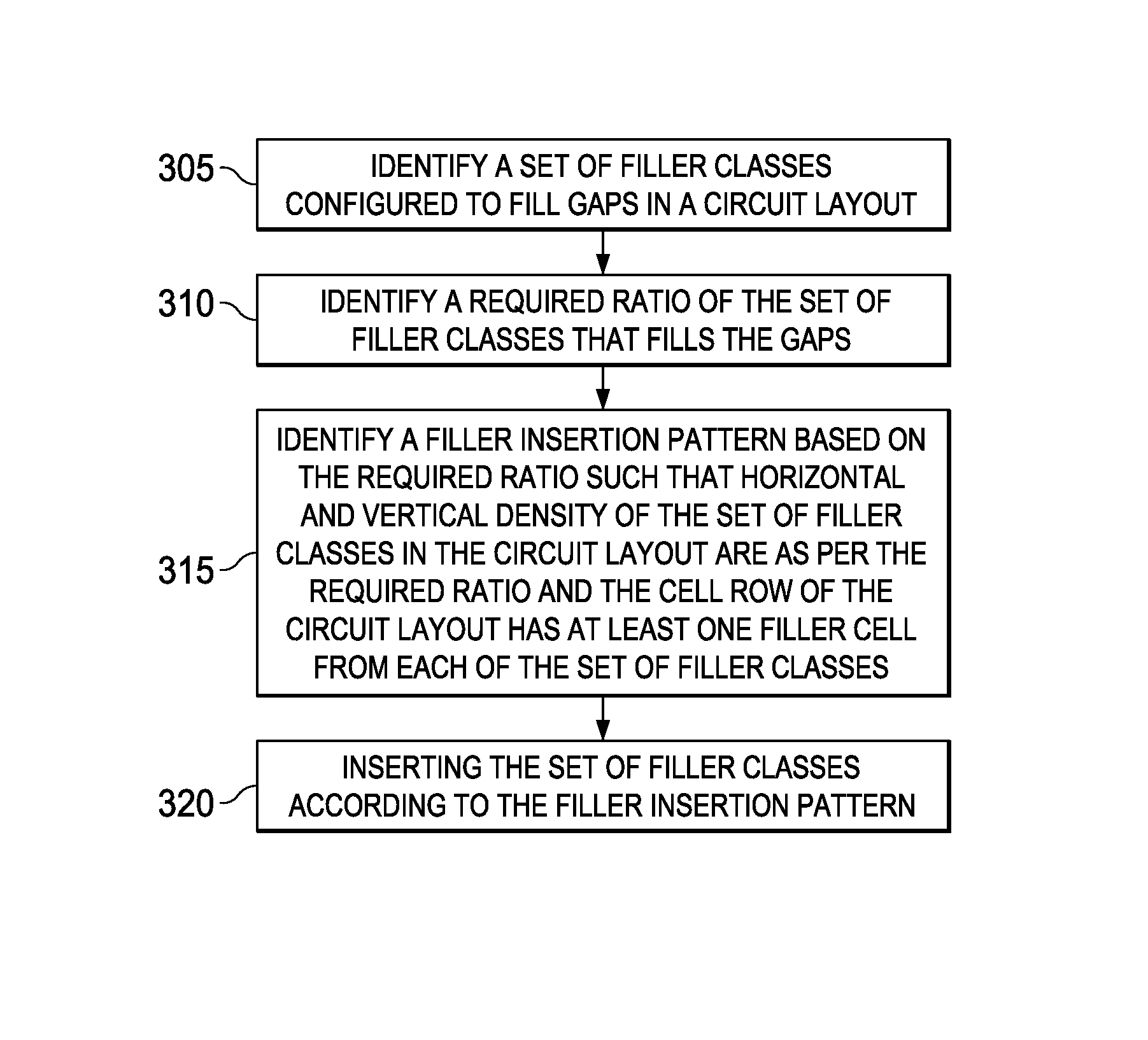
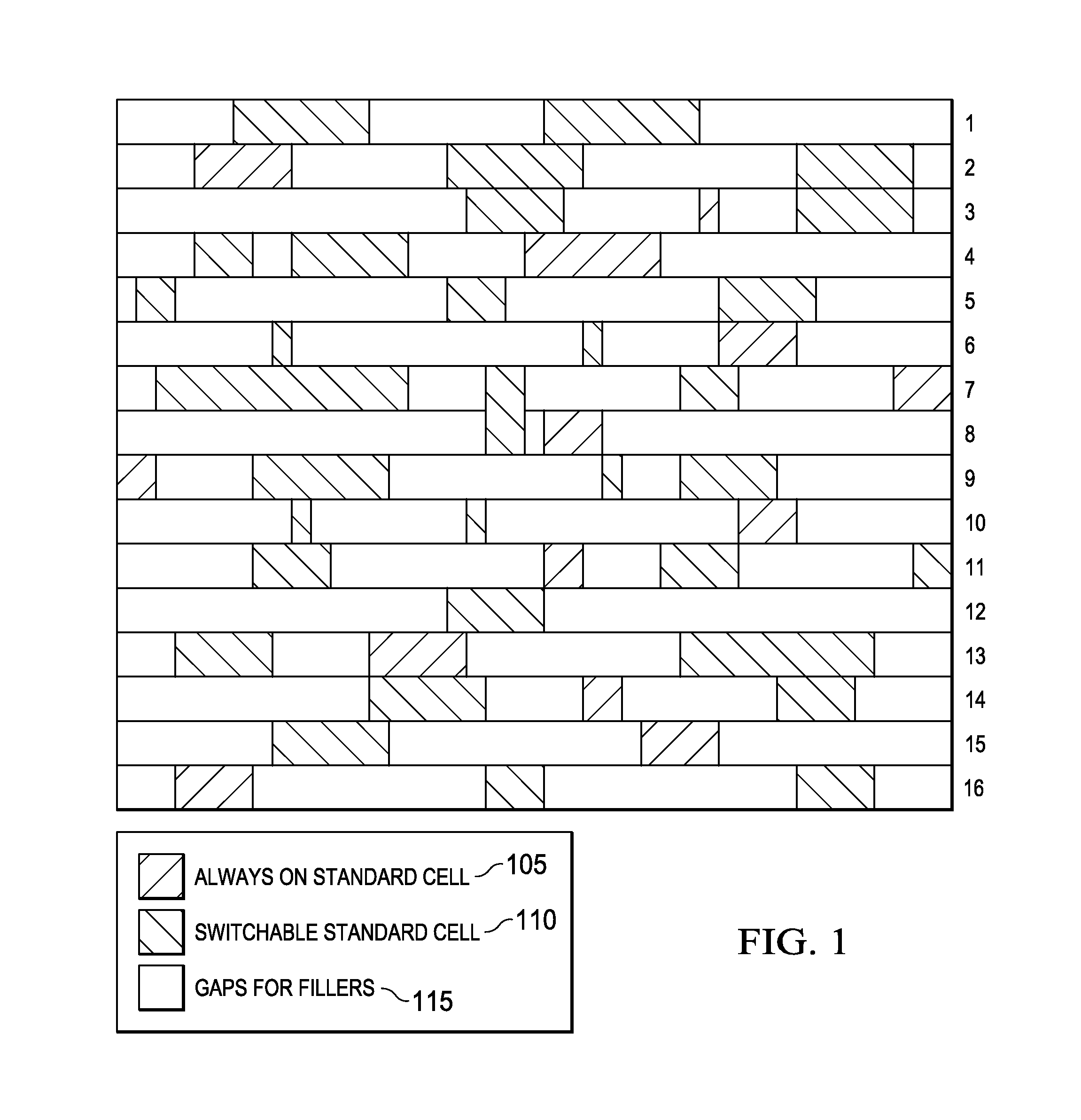
[0014]FIG. 1 illustrates placement of standard cells in a circuit layout by a place and route tool. In a standard cell layout of a low power design, gaps are created between standard cells. This is because it is not possible to have 100% utilization of the layout and also due to routing congestion. These gaps needs to be filled for N-well continuity and to eliminate the issues related to yield of the semiconductor chip.

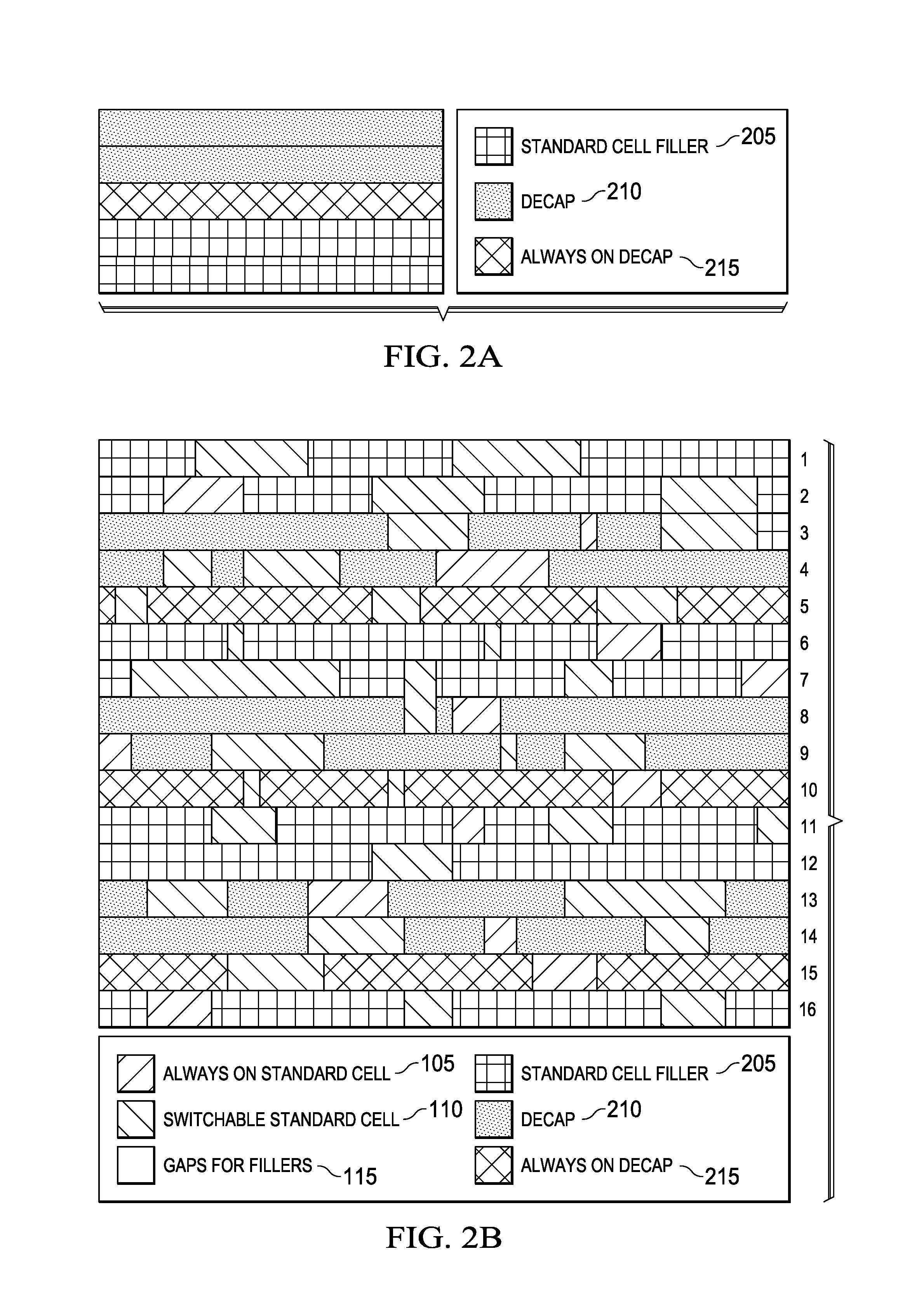
[0015]In low power design there are two kinds of standard cells based on power domain type. First is switchable standard cell and the second is always-on standard cell. Referring to FIG. 1, there are 16 rows of standard cells illustrated. Each standard cell row may have switchable standard cells 110, always-on standard cells 105 and gaps for fillers (gaps created between standard cells) 115.

[0016]The switchable standard cells 110 are powered off when the entire power domain turns off. The switchable standard cells 110 are powered by a local power supply. The always-on...


PUM


Abstract

A method for filler insertions in a circuit layout having a cell row of standard cells and gaps between the standard cells is disclosed. First, a set of filler classes, each filler class having a set of filler cells, is classified that are configured to fill the gaps depending on a design requirement. Then, a filler insertion pattern based on a required ratio is identified such that horizontal and vertical density of the set of filler classes in the circuit layout are as per the required ratio and the cell row of the circuit layout has at least one filler cell from each of the set of filler classes.

Description

TECHNICAL FIELD[0001]Embodiments of the disclosure relate to filler insertion in circuit layout for improving circuit performance.BACKGROUND[0002]The current physical design methodologies adopt filling the gaps in a circuit layout between the cell rows of standard cells with a single type of fillers. This leads to certain difficulties like engineering change order (ECO) capability and are not very efficient with power supply robustness. The ECO is not possible with single type of fillers because the base layers are also required to be changed. In a metal ECO change the base layers is not ideal.SUMMARY[0003]This Summary is provided to comply with 37 C.F.R. §1.73, requiring a summary of the invention briefly indicating the nature and substance of the invention. It is submitted with the understanding that it will not be used to interpret or limit the scope or meaning of the claims.[0004]An embodiment provides a method for filler insertions in a circuit layout having a cell row of stand...

Claims


Application Information

Patent Timeline
Patent Type & Authority Patents(United States)
IPC IPC(8): G06F17/50
CPCG06F17/5072G06F2217/78G06F30/392G06F2119/06
Inventor SOMAYAJI, ANANTHMODI, SOURAVDEWAL, SANIAMBIKAPATHY, SARAVANAN
Owner TEXAS INSTR INC
Why Eureka
Try Eureka