
Fluid-fed vacuum cutters

a vacuum cutter and vacuum feed technology, applied in the direction of manufacturing tools, transportation and packaging, sustainable manufacturing/processing, etc., can solve the problems of increasing manufacturing cost and lead tim

Active Publication Date: 2017-01-31
THE BOEING CO
View PDF26 Cites 8 Cited by
  • Summary
  • Abstract
  • Description
  • Claims
  • Application Information

AI Technical Summary

Benefits of technology

The patent text describes a tool for processing a location of a workpiece by using a vacuum and fluid to cut and remove material. The tool has a first passage for supplying vacuum and a second passage for supplying fluid. The tool also has a cutter that can be removed. The cutter includes a third and fourth passage for communication with the second passage. The tool can be manufactured by extruding a body and forming passages within it. The technical effects of the tool include improved processing accuracy and efficiency, as well as improved flexibility and adaptability for different workpiece materials and shapes.

Problems solved by technology

As such, the existing drilling methods require extensive cleanup, which increases manufacturing cost and lead times.

Method used


Image

  • Fluid-fed vacuum cutters
  • Fluid-fed vacuum cutters
  • Fluid-fed vacuum cutters

Examples


Embodiment Construction

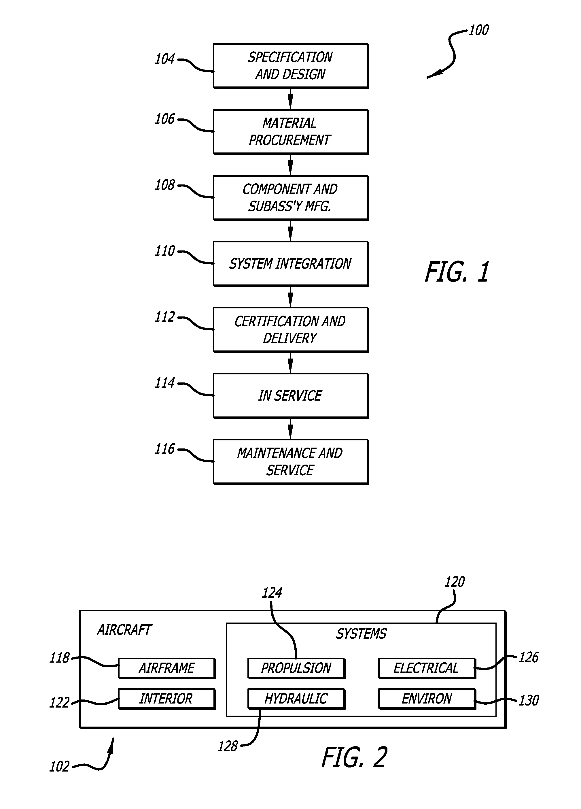
[0071]Examples of the disclosure may be described in the context of an aircraft manufacturing and service method 100 as shown in FIG. 1 and an aircraft 102 as shown in FIG. 2. During pre-production, exemplary method 100 may include specification and design 104 of the aircraft 102 and material procurement 106. During production, component and subassembly manufacturing 108 and system integration 110 of the aircraft take place. Thereafter, the aircraft 102 may go through certification and delivery 112 to be placed in service 114. While in service by a customer, the aircraft 102 is scheduled for routine maintenance and service 116 (which may also include modification, reconfiguration, refurbishment, and so on).

[0072]Each of the processes of the illustrative method 100 may be performed or carried out by a system integrator, a third party, and / or an operator (e.g., a customer). For the purposes of this description, a system integrator may include, without limitation, any number of aircraf...


PUM

PropertyMeasurementUnit
diameteraaaaaaaaaa
diameteraaaaaaaaaa
pressureaaaaaaaaaa

Abstract

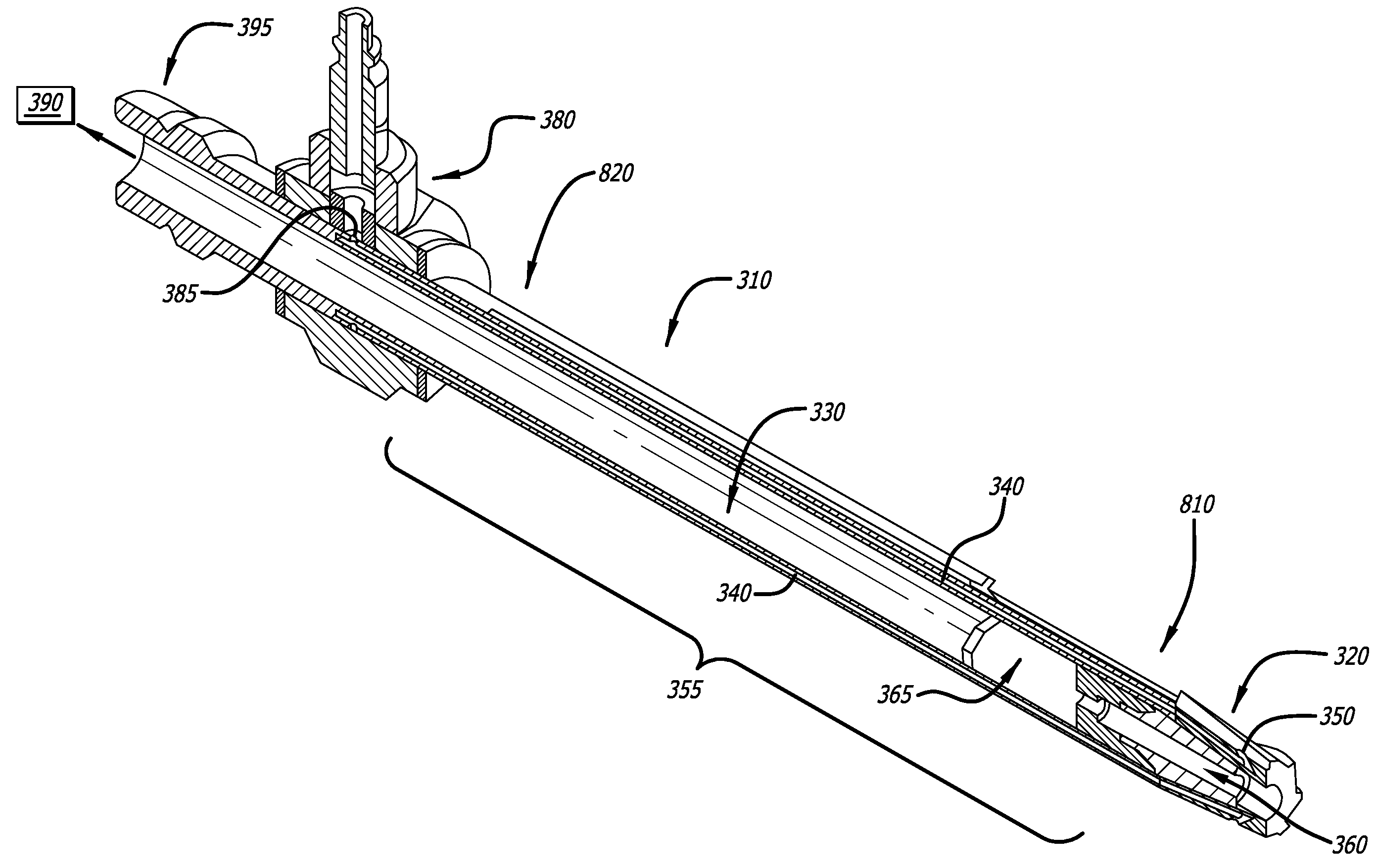
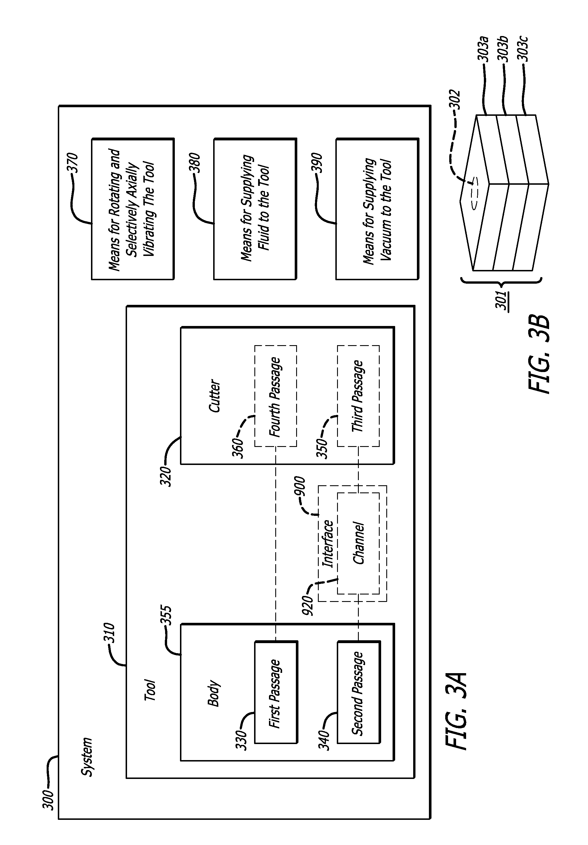
In one aspect of the disclosure, a system for processing a location of a workpiece is disclosed. The system includes a tool, including a first passage, configured to supply a vacuum to the location, and a second passage formed along the first passage, where the second passage is configured to supply a fluid to the location. The system also includes means for rotating and selectively axially vibrating the tool, means for supplying the fluid to the tool, and means for supplying the vacuum to the tool.

Description

BACKGROUND OF THE INVENTION[0001]Currently, external vacuum sources are commonly used to remove foreign-object debris (FOD), such as dust and chips, resulting from drilling operations. When processing parts that include metallic materials, fluid is typically supplied in large amounts at the processing location for lubricating and / or cooling purposes. As such, the existing drilling methods require extensive cleanup, which increases manufacturing cost and lead times.SUMMARY[0002]Accordingly, fluid-fed vacuum cutters may find utility.[0003]One example of the present disclosure relates to a system for processing a location of a workpiece. The system includes a tool, including a first passage, configured to supply a vacuum to the location, and a second passage formed along the first passage, where the second passage is configured to supply a fluid to the location. The system further includes means for rotating and selectively axially vibrating the tool, means for supplying the fluid to t...

Claims


Application Information

Patent Timeline
Patent Type & Authority Patents(United States)
IPC IPC(8): B23B27/10B23B35/00B23Q11/00B23B51/06B23D77/00
CPCB23B35/00B23B51/06B23D77/006B23Q11/006B23B2215/04B23B2251/68Y02P70/171Y10T408/03Y10T408/23Y10T408/45Y02P70/10
Inventor DELAND, JAMES ALBERTKESTERSON, MATTHEW GREGORY
Owner THE BOEING CO
Learn More