Supercharge Your Innovation With Domain-Expert AI Agents!

Gas sensor with a seal and method of making

a technology of gas sensor and sealing method, which is applied in the field of gas sensor, can solve the problems of ineffective talc seal and add cost and complexity to the process, and achieve the effects of simplifying manufacturing processes, minimizing components, and robust sealing arrangemen

Active Publication Date: 2017-01-31
DELPHI TECH IP LTD
View PDF8 Cites 0 Cited by
  • Summary
  • Abstract
  • Description
  • Claims
  • Application Information

AI Technical Summary

Benefits of technology

This design achieves a reliable and cost-effective sealing solution that prevents gas leakage between the sensing element and the shell, enhancing the durability and efficiency of the gas sensor.

Problems solved by technology

However, such a talc seal may not be effective under all conditions that the gas sensor may experience.
While this sealing arrangement may be effective, the mechanical seal requires an additional part which adds cost and complexity to the process.

Method used


Image

  • Gas sensor with a seal and method of making
  • Gas sensor with a seal and method of making
  • Gas sensor with a seal and method of making

Examples


Embodiment Construction

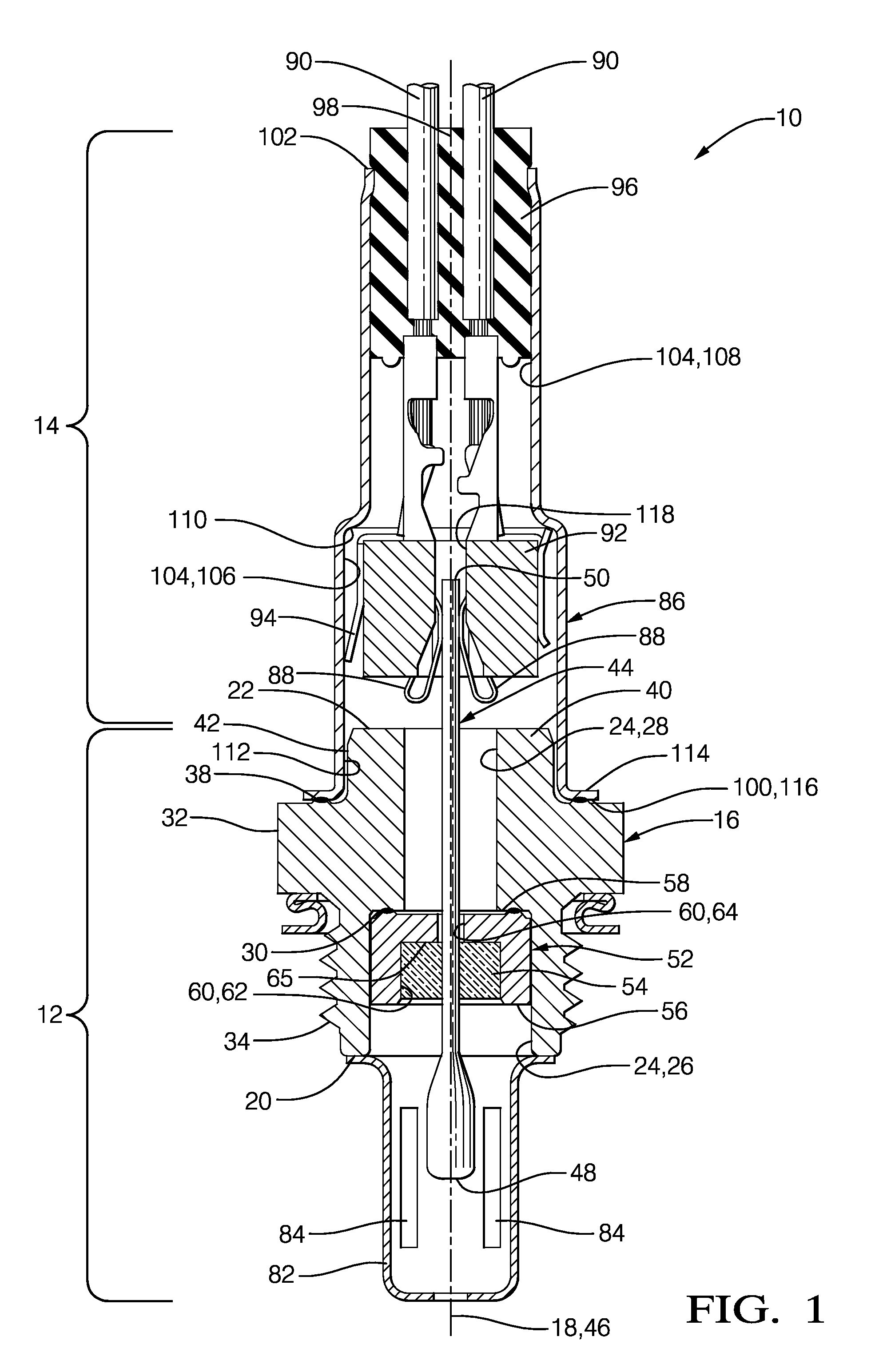
[0015]In accordance with a preferred embodiment of this invention and referring to FIG. 1, a gas sensor 10 is shown which generally includes a sensing subassembly 12 and an electrical harness subassembly 14. Gas sensor 10 is arranged to sense constituents of hot gases, by way of non-limiting example only, oxygen concentration levels of exhaust gases in an exhaust conduit (not shown) of an internal combustion engine (not shown).

[0016]Sensing subassembly 12 includes a metallic shell 16 which may be made of, for example only, 400 series stainless steel and which extends along a shell axis 18 from a shell first end 20 that is distal from electrical harness subassembly 14 to a shell second end 22 that is proximal to electrical harness subassembly 14.

[0017]A shell aperture 24 extends axially through shell 16 from shell first end 20 to shell second end 22 such that shell aperture 24 is centered about shell axis 18. Shell aperture 24 includes a shell aperture first section 26 which extends ...


PUM

PropertyMeasurementUnit
compressive forceaaaaaaaaaa
cross-sectional areaaaaaaaaaaa
concentrationsaaaaaaaaaa

Abstract

A gas sensor includes a metallic shell with a shell aperture extending therethrough along an axis; a metallic glass holder metallurgically sealed to the shell in order to prevent gases from passing between the glass holder and the shell, the glass holder including a glass holder aperture extending axially therethrough; a ceramic sensing element extending through the shell aperture and through the glass holder aperture; and a glass seal which seals between the sensing element and the glass holder in order to prevent gases from passing between the sensing element and the glass holder. A method of making the gas sensor is also provided.

Description

TECHNICAL FIELD OF INVENTION[0001]The present invention relates to a gas sensor, more particularly to such a gas sensor which includes a ceramic sensing element mounted in a metallic shell, even more particularly to an arrangement for sealing the sensing element to the shell, and still even more particularly to such a gas sensor for sensing exhaust constituents produced by an internal combustion engine.BACKGROUND OF INVENTION[0002]Gas sensors are known for determining composition concentrations in hot gases, for example, combustion exhaust gases produced by an internal combustion engine. A typical gas sensor includes a ceramic sensing element which includes electrodes at a sensing end thereof that are exposed to the gas being sensed while an opposing terminal end of the sensing element is fluidly isolated from the sensing end. The sensing element is commonly mounted in a metallic shell, and consequently, the sensing element must be sealed with respect to the shell in order to fluidl...

Claims


Application Information

Patent Timeline
Patent Type & Authority Patents(United States)
IPC IPC(8): G01D11/24B23K11/14F01N11/00
CPCG01D11/245B23K11/14F01N11/007F01N2260/20F01N2560/025
Inventor NELSON, CHARLES SCOTTPENAMALLI, GOPINATH REDDYMCCAULEY, KATHRYN M.
Owner DELPHI TECH IP LTD
Features
  • R&D
  • Intellectual Property
  • Life Sciences
  • Materials
  • Tech Scout
  • Unparalleled Data Quality
  • Higher Quality Content
  • 60% Fewer Hallucinations
Learn More