

Valve sealing arrangement
- Summary
- Abstract
- Description
- Claims
- Application Information
AI Technical Summary
Benefits of technology
Problems solved by technology
Method used
Image

Examples
Embodiment Construction
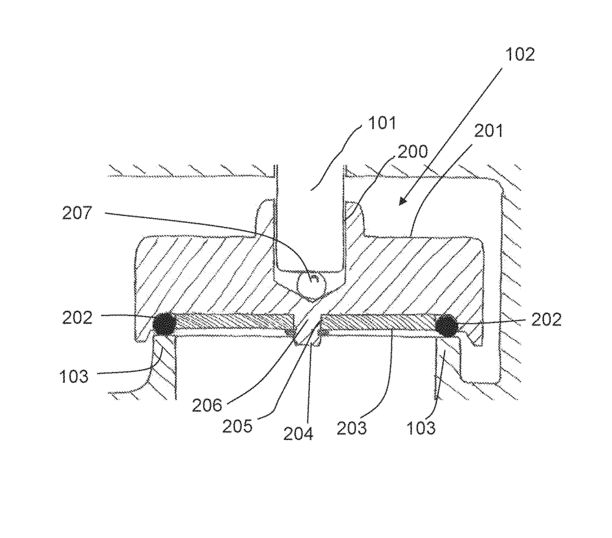
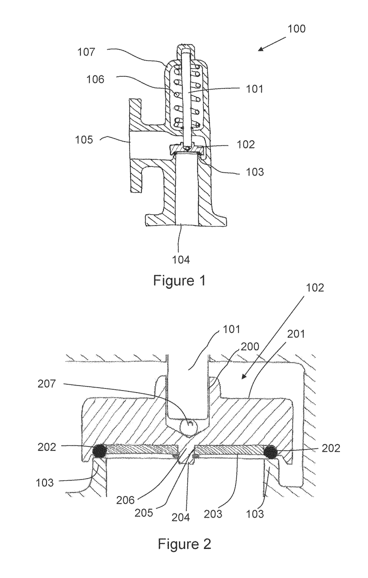
[0035]Referring to FIG. 1, a valve 100 comprises a valve body 107 which defines an inlet 104 and an outlet 105 at 90 degrees to each other for fluid which may pass through the valve following an ‘L’ shaped flow path. Fluid flow from the inlet 104 to the outlet 105 is controlled by a valve disk 102 which can seal or open the flow path between the valve outlet and inlet. Part of the body forms a valve seat 103 which is a flat annular surface which encompasses the flow path from the inlet. The valve disk 102 is positioned directly above the valve seat 103 at the 90 degree bend between the outlet and inlet and retains a sealing member in its base. In this embodiment the sealing member is a PTFE ‘O’ ring. When the valve disk is forced against the valve seat the sealing member forms a leak proof seal between the two.
[0036]The valve disk 102 is located on the end of a spindle 101 which is slidably mounted on the valve body 107 and is acted on by a spring 106 which applies a biasing force t...
PUM
 Abstract
Description
Claims
Application Information