Parking brake adjustment for an aircraft having an electric brake system

a technology of electric brakes and parking brakes, which is applied in the field of aircraft braking systems, can solve the problems of increased or decreased clamping force, and increased clamping force, so as to reduce the risk of damage to brake components, reduce weight and size of aircraft batteries, and prolong the battery life of aircra

Inactive Publication Date: 2007-04-19
THE BOEING CO
View PDF2 Cites 45 Cited by
  • Summary
  • Abstract
  • Description
  • Claims
  • Application Information

AI Technical Summary

Benefits of technology

[0004] A method and system are provided for adjusting a parking brake for an aircraft having an electric brake system. Adjustment of a parking brake as described herein is advantageous because the system and procedures can compensate for thermal expansion or contraction of components of a brake mechanism. Adjustment of an aircraft parking brake to compensate for transient thermal characteristics of the brake is desirable for preventing the aircraft from rolling while in a parked condition and also for reducing the risk of damaging brake components. Additionally, embodiments of the system and methods provided herein are capable of conserving power, thereby extending the battery life of the aircraft and potentially decreasing the weight and size of the aircraft battery.

Problems solved by technology

These increased temperatures and the subsequent cooling period may cause thermal expansion and contraction of brake components which may result in increased or decreased clamping force.
If this occurs after an aircraft has been parked and the parking brake has been set, the integrity of the parking brake may be compromised.
On the other hand, an increase in clamping force may be seen as brake components cool down and contract, the result of which may be damage to components.
In an electric brake system, however, where an electric motor and gear train is used to compress the brake, there is no automatic adjustment mechanism that maintains pressure on the brake when the brake heats or cools.
The brake either loses compression pressure, or the brake pressure increases and causes the electric motor and gear train to be stressed or damaged.

Method used


Image

  • Parking brake adjustment for an aircraft having an electric brake system
  • Parking brake adjustment for an aircraft having an electric brake system
  • Parking brake adjustment for an aircraft having an electric brake system

Examples


Embodiment Construction

[0017] The following detailed description is merely illustrative in nature and is not intended to limit the embodiments of the invention or the application and uses of such embodiments. Furthermore, there is no intention to be bound by any expressed or implied theory presented in the preceding technical field, background, brief summary or the following detailed description.

[0018] Embodiments of the invention may be described herein in terms of functional and / or logical block components and various processing steps. It should be appreciated that such block components may be realized by any number of hardware, software, and / or firmware components configured to perform the specified functions. For example, an embodiment of the invention may employ various integrated circuit components, e.g., memory elements, digital signal processing elements, logic elements, look-up tables, or the like, which may carry out a variety of functions under the control of one or more microprocessors or oth...


PUM


Abstract

A system and procedures for adjusting a parking brake for an aircraft having an electric brake system are disclosed. Adjustment of a parking brake as described herein can compensate for thermal expansion or contraction of components of a parking brake mechanism, generally seen during and subsequent to an aircraft landing. Procedures for adjusting an aircraft parking brake as disclosed herein include setting the aircraft brakes to an initial state, comparing a measured elapsed time to a threshold time, measuring a brake temperature, adjusting the brakes to achieve a desired clamping force or brake actuator position, and engaging a friction brake in order to conserve power needed by an electric brake actuator.

Description

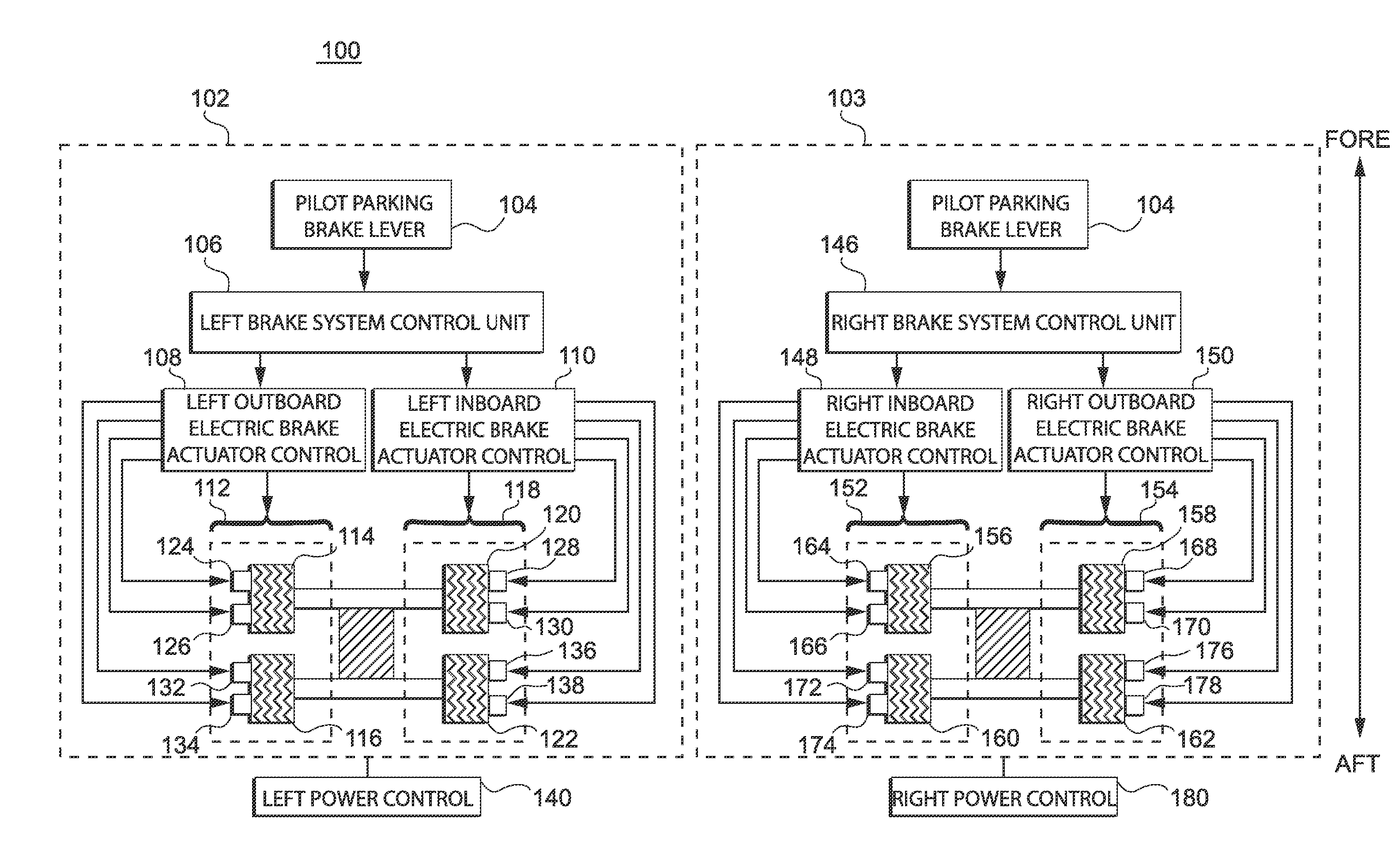
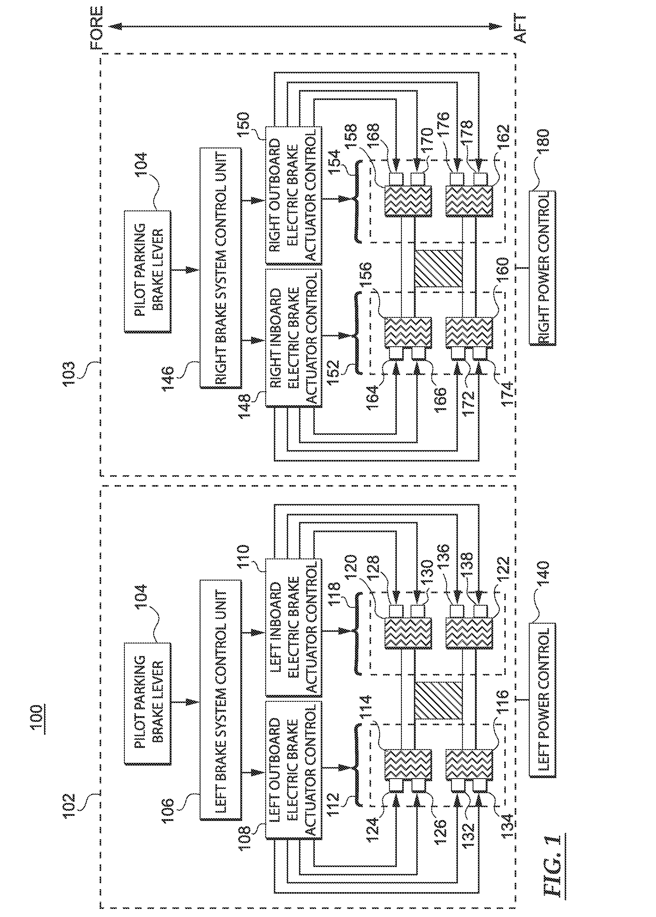
TECHNICAL FIELD [0001] Embodiments of the present invention relate generally to aircraft braking systems. More particularly, embodiments of the present invention relate to a method and system for adjusting a parking brake of an electric brake system in response to changing brake temperature. BACKGROUND [0002] Upon landing and braking, aircraft brake components will see greatly increased temperatures due to braking friction. These increased temperatures and the subsequent cooling period may cause thermal expansion and contraction of brake components which may result in increased or decreased clamping force. Decreased clamping force is generally experienced as brake components expand with increased temperature. If this occurs after an aircraft has been parked and the parking brake has been set, the integrity of the parking brake may be compromised. On the other hand, an increase in clamping force may be seen as brake components cool down and contract, the result of which may be damage...

Claims


Application Information

Patent Timeline
Patent Type & Authority Applications(United States)
IPC IPC(8): F16D65/36F16D65/28H04L12/26H04L12/56
CPCB60T8/00B60T8/1703B60T13/741B60T17/221H04W36/12Y02D30/70
Inventor GRIFFITH, T. TODDGODO, ERIK
Owner THE BOEING CO
Why Eureka
Try Eureka