Large-diameter earth pressure balance shield machine

An earth pressure balance and shield machine technology, applied in the field of shield machines, can solve the problems of reducing the working efficiency of the shield machine, decreasing the driving speed, and the deflection of the tunnel axis, so as to speed up the propulsion speed and work efficiency, and reduce the propulsion force. , the effect of reducing the chance of slush cake

Inactive Publication Date: 2010-08-11
SHANGHAI LIXING ENG TECH DEV
View PDF0 Cites 48 Cited by
  • Summary
  • Abstract
  • Description
  • Claims
  • Application Information

AI Technical Summary

Problems solved by technology

[0006] (2) The rolling of the shield machine body will produce the following adverse consequences: a) affect the assembly of the segments, or even damage the segments; b) cause the deflection of the tunnel axis; c) sometimes, in order to optimize the flow of muck, The cutterhead must rotate in a specified direction, but since the cutterhead can only rotate in one direction (to correct the rolling of the shield machine), it is not possible to correct the attitude of the shield by changing the direction of rotation of the cutterhead; d) when the cutterhead is used in one direction During rotating construction, in order to offset the moment caused by the deflection of the propulsion cylinder, the moment must be transmitted to the tunnel lining to a certain extent
However, if the rolling occurs in a large shield (more than 11 meters in diameter), the damage and consequences caused are very serious, and it is very difficult to correct it.
[0009] 2. The mud cake problem
When the mud cake is generated, the thrust of the shield machine is much higher than the usual normal thrust, the tunneling speed drops sharply, and the torque of the cutter head will also increase, which greatly reduces the working efficiency of the shield machine

Method used


Image

  • Large-diameter earth pressure balance shield machine
  • Large-diameter earth pressure balance shield machine
  • Large-diameter earth pressure balance shield machine

Examples


Embodiment 1

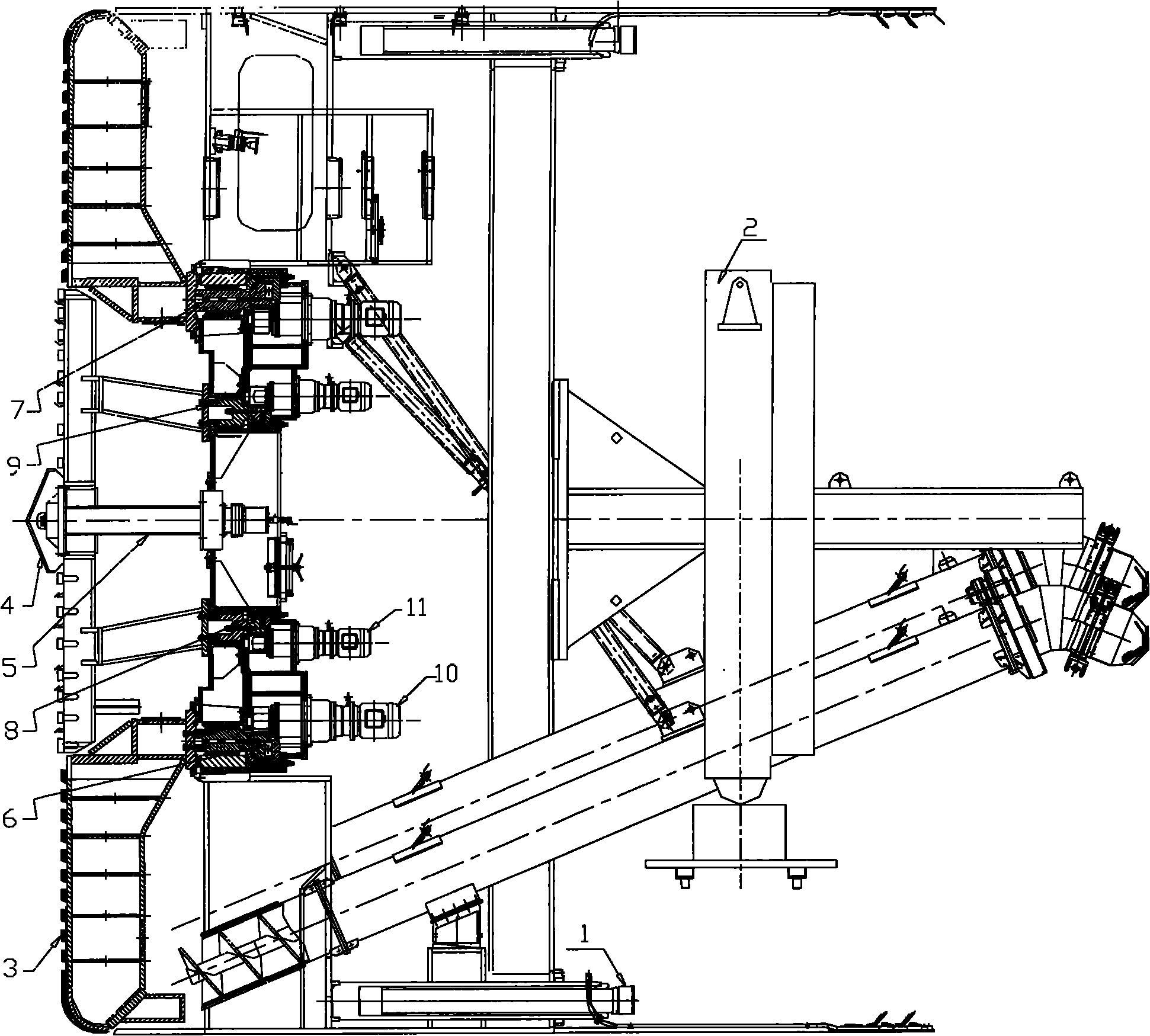
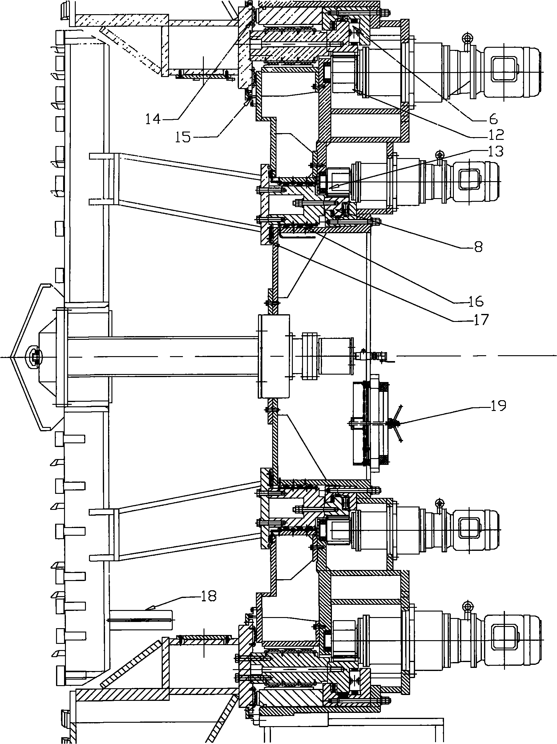
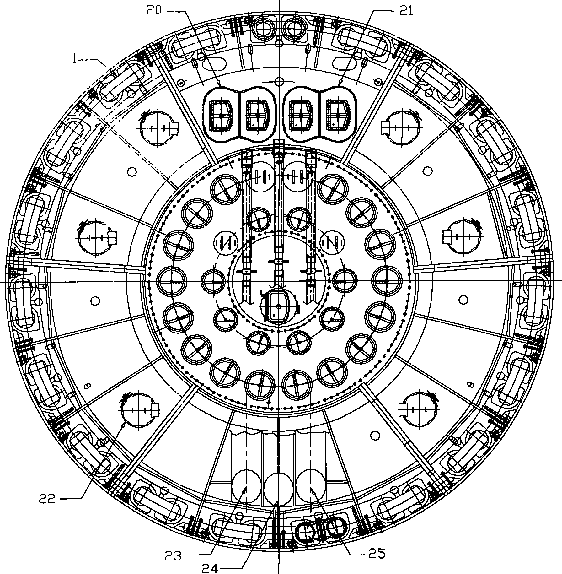
[0035] Such as Figure 1 ~ Figure 4 As shown, a large-diameter (above 11m) earth pressure balance shield machine designed based on Shanghai's geological conditions includes a cutter head, a cutter head drive unit, a propulsion cylinder 1, an assembly machine 2, a screw conveyor, and a frame.

[0036] The cutter head is a double cutter head, and the double cutter head includes an integral peripheral large cutter head 3 and an independent central cutter head 4. The outer peripheral large cutter head 3 includes eight groups of spoke panel knife arms 31, and the independent central cutter head 4 and the central cutter head The center rotation 5 is connected, and the independent center cutter head 4 includes six sets of spoke panel knife arms 41, and the technical parameters of the two are shown in Table 1:

[0037] Table 1 The technical parameters of the peripheral large cutterhead and independent central cutterhead

[0038] Peripheral cutter head

technical parameter...


PUM


Abstract

The invention relates to a large-diameter earth pressure balance shield machine. The machine comprises a cutterhead, a cutterhead drive part, a propulsion oil cylinder, an erector, spiral conveyors and a frame; the cutterhead is a double-cutterhead which comprises a peripheral large cutterhead and an independent central cutterhead; the cutterhead drive part comprises two driving mechanisms which drive the peripheral large cutterhead and the independent central cutterhead respectively; and the peripheral large cutterhead and the independent central cutterhead rotate independently and bidirectionally. Compared with the prior art, the shield machine adopts the double-cutterhead design, greatly optimizes a cutting speed of the cutterhead on a soil body, further improves a propulsion speed of the shield, optimizes the disturbance effect of the cutterhead on the soil body, and prevents the rolling of a shield machine body; different opening rates are designed on the cutterhead and are suitable for different situations of a central part and a peripheral part when a tunnel is advanced; and three spiral conveyors discharge soil, effectively control the posture of the shield, and prevent the deviation of a tunnel axis.

Description

technical field [0001] The invention relates to a shield machine, in particular to a large-diameter earth pressure balance shield machine. Background technique [0002] At present, shield machines used in the world generally use a single cutter head for soil cutting. In actual use, the shield machine with a single cutter head has the following problems: [0003] 1. The rolling problem of the shield body [0004] (1) The rolling of the shield body is a phenomenon that the shield body rolls because the torque generated by the cutterhead is greater than the frictional moment between the shell of the shield machine and the tunnel wall when the cutterhead cuts the soil on the excavation surface. In some special formations, such as two formations with large differences in structure and strength, the upper layer is a soft soil layer and the lower layer is a hard rock layer. When the shield tunnels at the interface between the two strata, due to the large difference in lithology ...

Claims


Application Information

Patent Timeline
Patent Type & Authority Applications(China)
IPC IPC(8): E21D9/00E21D9/08
Inventor 陈维明
Owner SHANGHAI LIXING ENG TECH DEV
Why Eureka
Try Eureka