Impact tools

a technology of impact tools and tools, applied in the direction of wrenches, power driven tools, screwdrivers, etc., can solve the problems of significant vibration of impact tools, impact tools designed to operate on hard joints often perform inadequately on soft joints, etc., and achieve the effect of reducing the rotational speed of the hammer

Active Publication Date: 2017-02-21
INGERSOLL RAND IND U S INC
View PDF18 Cites 24 Cited by
  • Summary
  • Abstract
  • Description
  • Claims
  • Application Information

AI Technical Summary

Benefits of technology

[0007]According to another aspect, a method of operating an impact tool may comprise rotating a hammer of the impact tool about an axis to cause the hammer to translate along the axis in a first direction to impact an anvil of the impact tool, thereby causing rotation of the anvil about the axis and reducing a rotational speed of the hammer in response to a distance that the hammer has rebounded in a second direction after impacting the anvil exceeding a threshold distance, the second direction being opposite the first direction.

Problems solved by technology

For example, impact tools designed to operate on soft joints (i.e., low rebound applications where the majority of the impacting energy is transferred into the joint) often result in significant vibration of the impact tool when operating on hard joints (i.e., high rebound applications) due to the motor operating at higher speeds.
Conversely, impact tools designed to operate on hard joints often perform inadequately on soft joints due to the motor operating at lower speeds.

Method used


Image

  • Impact tools
  • Impact tools
  • Impact tools

Examples


Embodiment Construction

[0020]While the concepts of the present disclosure are susceptible to various modifications and alternative forms, specific exemplary embodiments thereof have been shown by way of example in the figures and will herein be described in detail. It should be understood, however, that there is no intent to limit the concepts of the present disclosure to the particular forms disclosed, but on the contrary, the intention is to cover all modifications, equivalents, and alternatives falling within the spirit and scope of the present disclosure.

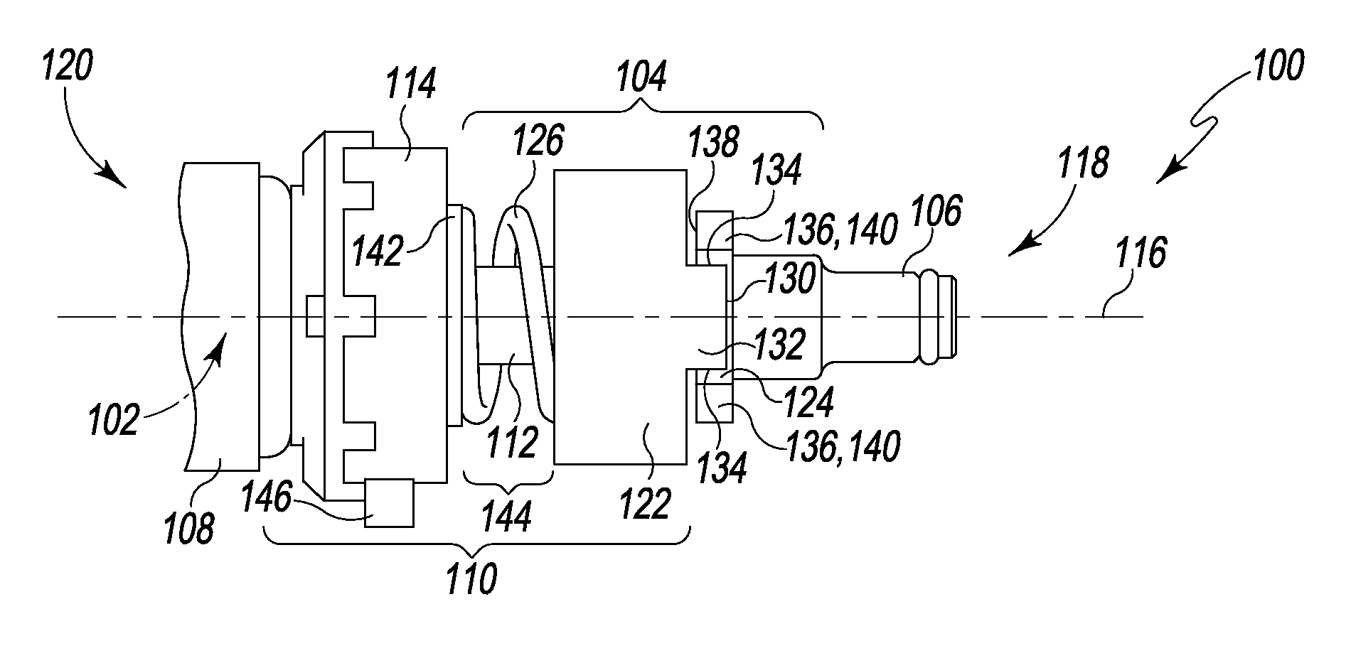
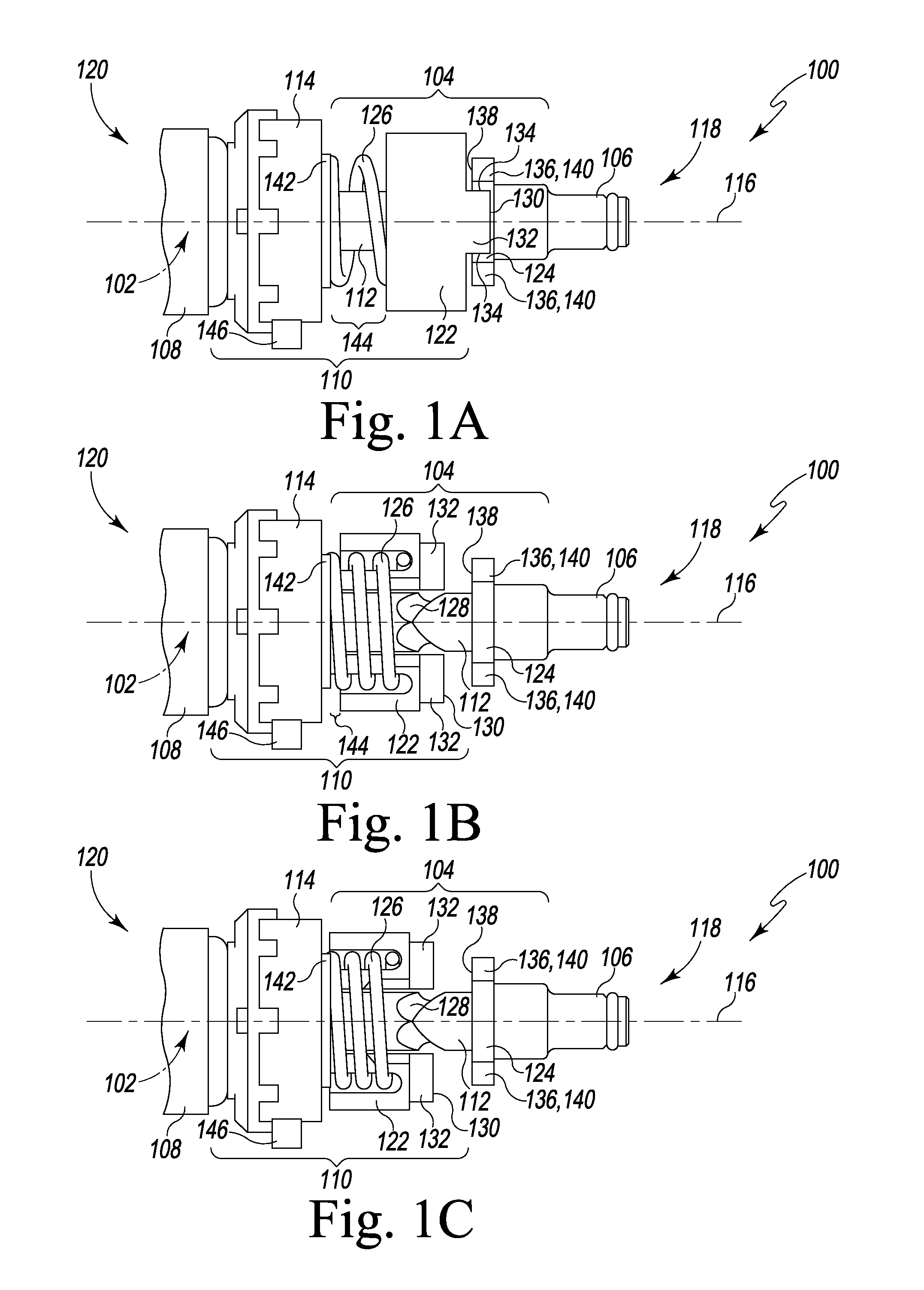
[0021]Referring generally to FIGS. 1A-C, profile and partial cross-sectional views of selected components of one illustrative embodiment of an impact tool 100 are shown. In particular, FIG. 1A shows a profile view of a ball-and-cam impact mechanism 104 of the impact tool 100 (along with related components), while FIGS. 1B and 1C are partial cross-sectional views in which only the hammer 122 is shown in cross section (i.e., all other components are sho...


PUM


Abstract

In at least one illustrative embodiment, an impact tool may comprise an impact mechanism including a hammer and an anvil. The hammer may be configured to rotate about an axis and to translate along the axis to impact the anvil to cause rotation of the anvil about the axis. The impact tool may further comprise a motor, a drive train, an inertial sensor, and an electronic controller. The drive train may be configured to transfer rotation from the motor to the hammer of the impact mechanism. The inertial sensor may be configured to sense an acceleration of the drive train along the axis. Further, the electronic controller may be operably coupled to the motor and to the inertial sensor and configured to decrease a rotational speed of the motor in response to determining that the acceleration of the drive train has exceeded a threshold acceleration.

Description

TECHNICAL FIELD[0001]The present disclosure relates, generally, to impact tools and, more particularly, to impact tools having vibration reduction control.BACKGROUND[0002]An impact wrench is one illustrative embodiment of an impact tool, which may be used to install and remove threaded fasteners. An impact wrench generally includes a motor coupled to an impact mechanism that converts the torque of the motor into a series of powerful rotary blows (i.e., impacts) directed from one or more hammers to an anvil coupled to an output shaft. In a ball-and-cam type impact mechanism, the hammer both rotates about an axis and translates along that axis to impact the anvil. The translation of the hammer (and, hence, the timing of the impacts with the anvil) is mechanically controlled by one or more balls disposed in cam grooves formed between the hammer and a camshaft, as well as a spring that biases the hammer. After each impact with the anvil, the hammer rebounds rotationally around the axis ...

Claims


Application Information

Patent Timeline
Patent Type & Authority Patents(United States)
IPC IPC(8): B25B21/02B25B23/147
CPCB25B21/02B25B23/1475
Inventor BARTOSZEK, JASON CHRISTOPHER
Owner INGERSOLL RAND IND U S INC
Why Eureka
Try Eureka