
Operating method for a positioning system

a positioning system and operating method technology, applied in the direction of process and machine control, program control, instruments, etc., can solve the problems of limited flexibility of component variants and great effort for control technology

Active Publication Date: 2017-02-21
BA ASSEMBLY & TURNKEY SYST
View PDF10 Cites 0 Cited by
  • Summary
  • Abstract
  • Description
  • Claims
  • Application Information

AI Technical Summary

Benefits of technology

The patent text describes an improved and alternative operating method for a positioning system that is suitable for aircraft structural assembly. The system uses multiple positioners with manipulators to grasp and position components. The manipulators can synchronously manipulate the components, allowing for compensation of any deformation caused by the weight of the component. The system can also use coordinated positioning units for shell assembly, but this method has limited flexibility. The use of the positioning system can lead to a more efficient and flexible assembly process for aircraft.

Problems solved by technology

However, this has the disadvantage that, due to the design as a shape-defining frame, the degree of flexibility for component variants is limited.
However, this configuration has the disadvantage that a very great effort is required for the control technology.

Method used


Image

  • Operating method for a positioning system
  • Operating method for a positioning system
  • Operating method for a positioning system

Examples


Embodiment Construction

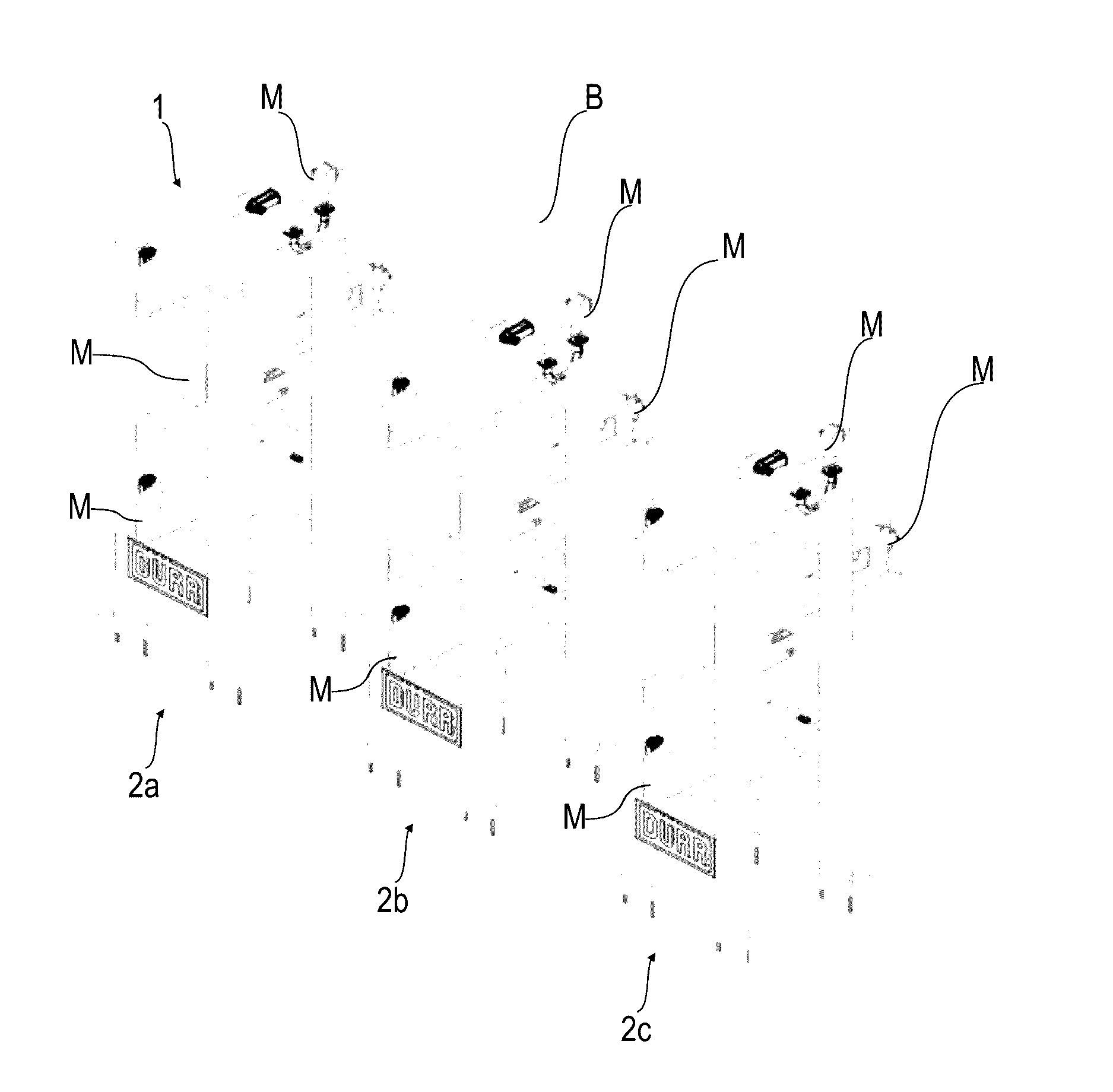
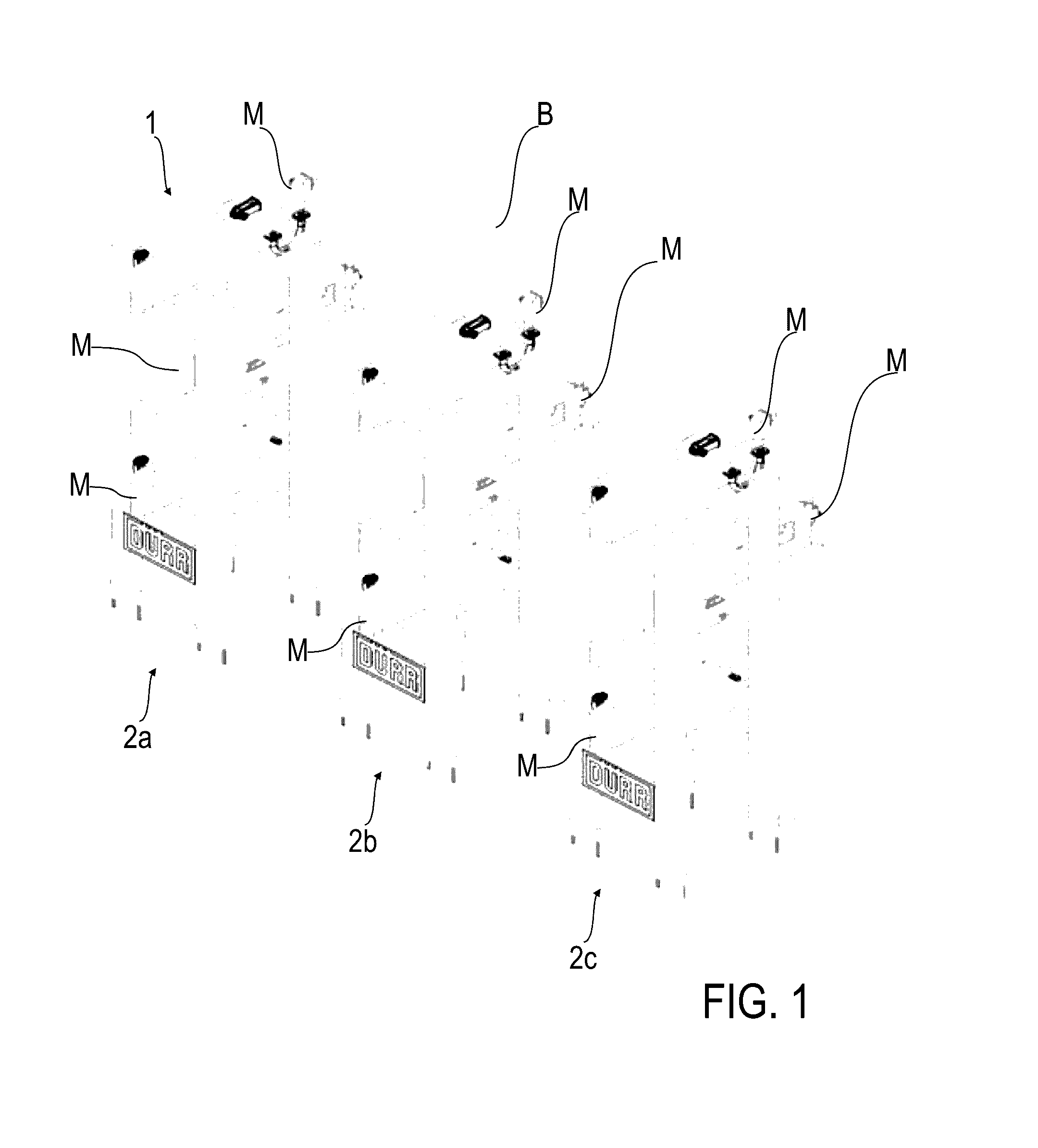
[0053]FIG. 1 shows a perspective view of a positioning system 1 according to one embodiment, which comprises a plurality of positioners 2a, 2b, 2c. Each of the positioners 2a, 2b, 2c comprises three manipulators which, for the sake of clarity, are all identified with the reference sign M. The manipulators M can have the same or different designs and are configured to grasp a component B in the form of a shell segment and to manipulate it synchronously while it is commonly grasped by the manipulators M.

[0054]The situation shown in FIG. 1 can be an initial situation of the component B in which the component B has been brought by a crane construction (not shown) before it was grasped by at least some of the manipulators M and removed.

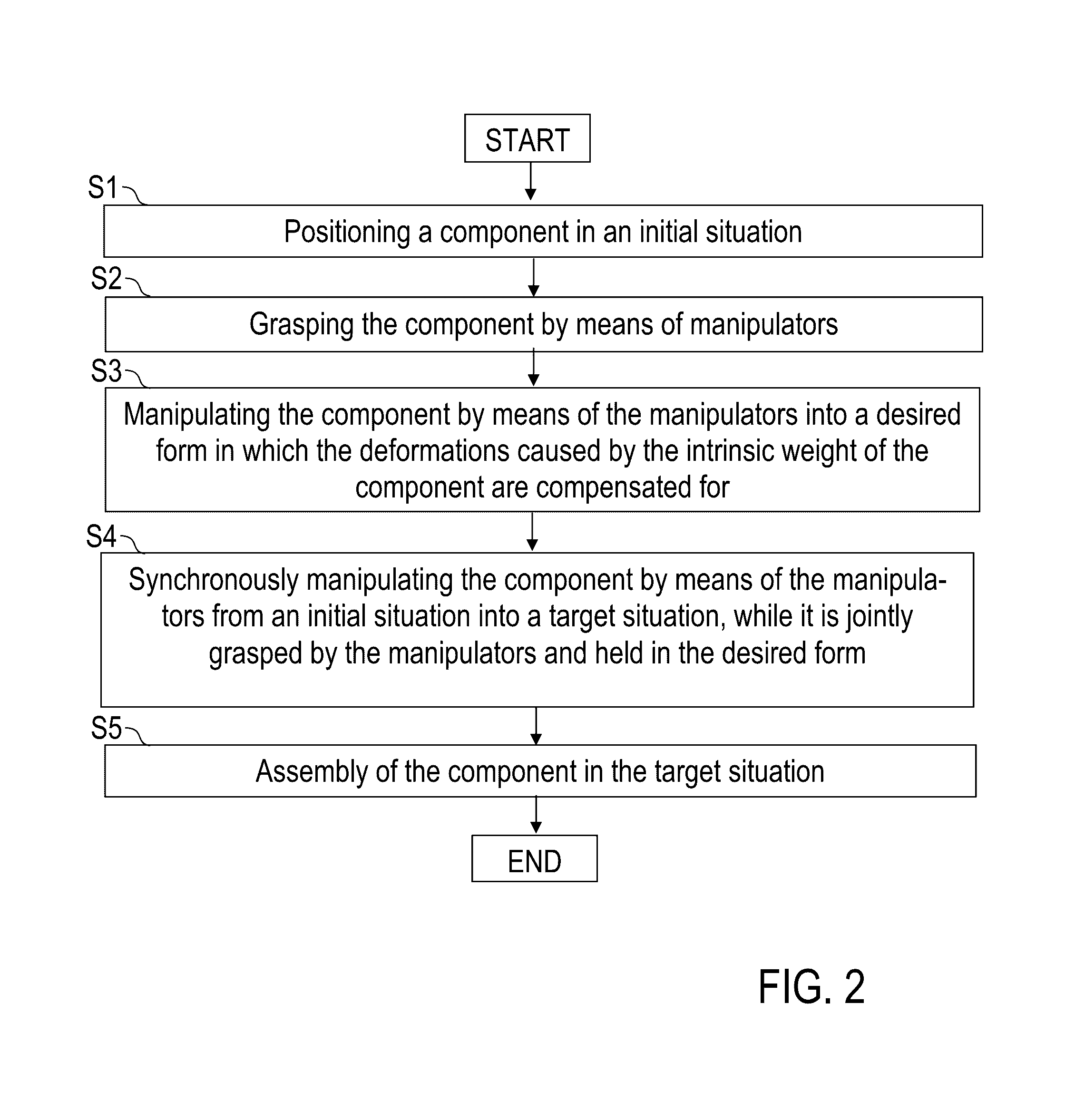
[0055]The component B is flexionally flaccid and, in the absence of suitable countermeasures, has a deformation caused by the intrinsic weight thereof. The manipulators M are configured so as to grasp the component B in the initial situation in a desired f...


PUM

PropertyMeasurementUnit
movementaaaaaaaaaa
intrinsic weightaaaaaaaaaa
reference movement parametersaaaaaaaaaa

Abstract

The invention relates to an operating method for a positioning system 1, in particular for the structural assembly of aircraft, wherein the positioning system 1 comprises a plurality of positioners 2a, 2b, 2c, each of which has at least one manipulator M. The manipulators M grasp a component B and manipulate it in a synchronized manner, while it is jointly grasped by the manipulators M.

Description

CROSS-REFERENCE TO RELATED APPLICATIONS[0001]The subject patent application claims priority to and all the benefits of International Patent application No. PCT / EP2012 / 004308 filed on Oct. 15, 2012, which claims priority to German Patent Application No. DE 10 2011 116 437.9 filed on Oct. 19, 2011, both of which are herein incorporated by reference in their entirety.BACKGROUND AND SUMMARY[0002]An operating method for a positioning system advantageously comprises a plurality of positioners, each of which may have at least one manipulator for manipulating a component. A possible use is the structural assembly of aircraft wherein shell segments are assembled into fuselage sections, the fuselage sections are then possibly positioned relative to one another and joined into a fuselage and subsequently, for example, the bearing structure, the empennages and the undercarriage are assembled onto the fuselage.[0003]In conventional structural assemblies of aircraft in which components in the for...

Claims


Application Information

Patent Timeline
Patent Type & Authority Patents(United States)
IPC IPC(8): G06F7/00B64F5/00B25J9/16B25J9/00B23P21/00
CPCB64F5/10B25J9/0084B23P21/00B25J9/1682G05B2219/32285G05B2219/39121G05B2219/40417G05B2219/45071Y10T29/49826B25J9/16B64F5/00
Inventor MEI.BETA.NER, ALEXANDERHACKER, JENSPOPPE, DIRKBIYIKLIOGLU, NIHATMBAREK, TAOUFIK
Owner BA ASSEMBLY & TURNKEY SYST
Learn More