Tracking method and optical input device using the same

a tracking method and optical input technology, applied in the field can solve the problems of time-consuming, power constraints, and general technical constraints achieve the effect of increasing the tracking performance of optical input devices, efficient and accurate identification of peak correlation values

Active Publication Date: 2017-03-07
PIXART IMAGING INC
View PDF17 Cites 0 Cited by
  • Summary
  • Abstract
  • Description
  • Claims
  • Application Information

AI Technical Summary

Benefits of technology

[0007]Accordingly, the present disclosure provides a tracking method and an optical input device using the same. The tracking method can efficiently and accurately identify the peak correlation value between frames captured and determine the motion of an optical input device while the optical input device operates. Thereby, increases the tracking performance of the optical input device.
[0013]To sum up, exemplary embodiments of the present disclosure provide a tracking method and an optical input device using the same, in which when a peak correlation value computed is found at the corner of a predetermined correlation window in a process of comparing frames captured, another correlation between frames centering on the position of the peak correlation value is automatically computed for verifying whether the peak correlation value is the actual peak or there is another peak exist outside the predetermined correlation window, so as to increase the accuracy of tracking the relative movement of the optical input device can be quick and efficiently achieved.

Problems solved by technology

Even though the pixel by pixel correlation scheme in practice could yield accurate result but could be time consuming as it requires intensive computations.
The optical input device generally is subject to specific technical constraints, particularly time and power constraints.
Moreover, since optical input device is generally battery-powered, thus the longer the image processing time, the more power will be consumed.

Method used


Image

  • Tracking method and optical input device using the same
  • Tracking method and optical input device using the same
  • Tracking method and optical input device using the same

Examples


Embodiment Construction

[0020]Reference will now be made in detail to the exemplary embodiments of the present disclosure, examples of which are illustrated in the accompanying drawings. Wherever possible, the same reference numbers are used in the drawings and the description to refer to the same or like parts.

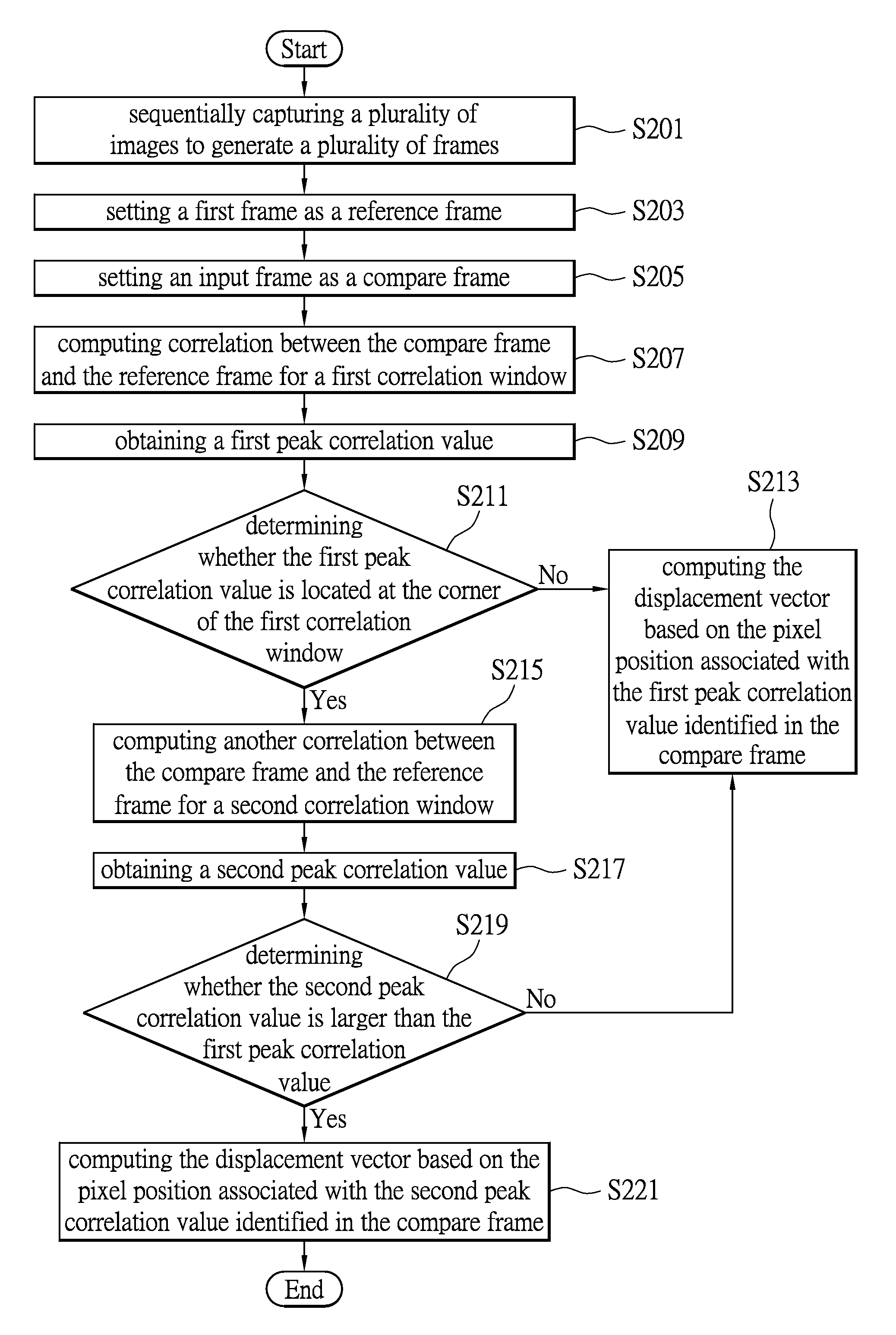
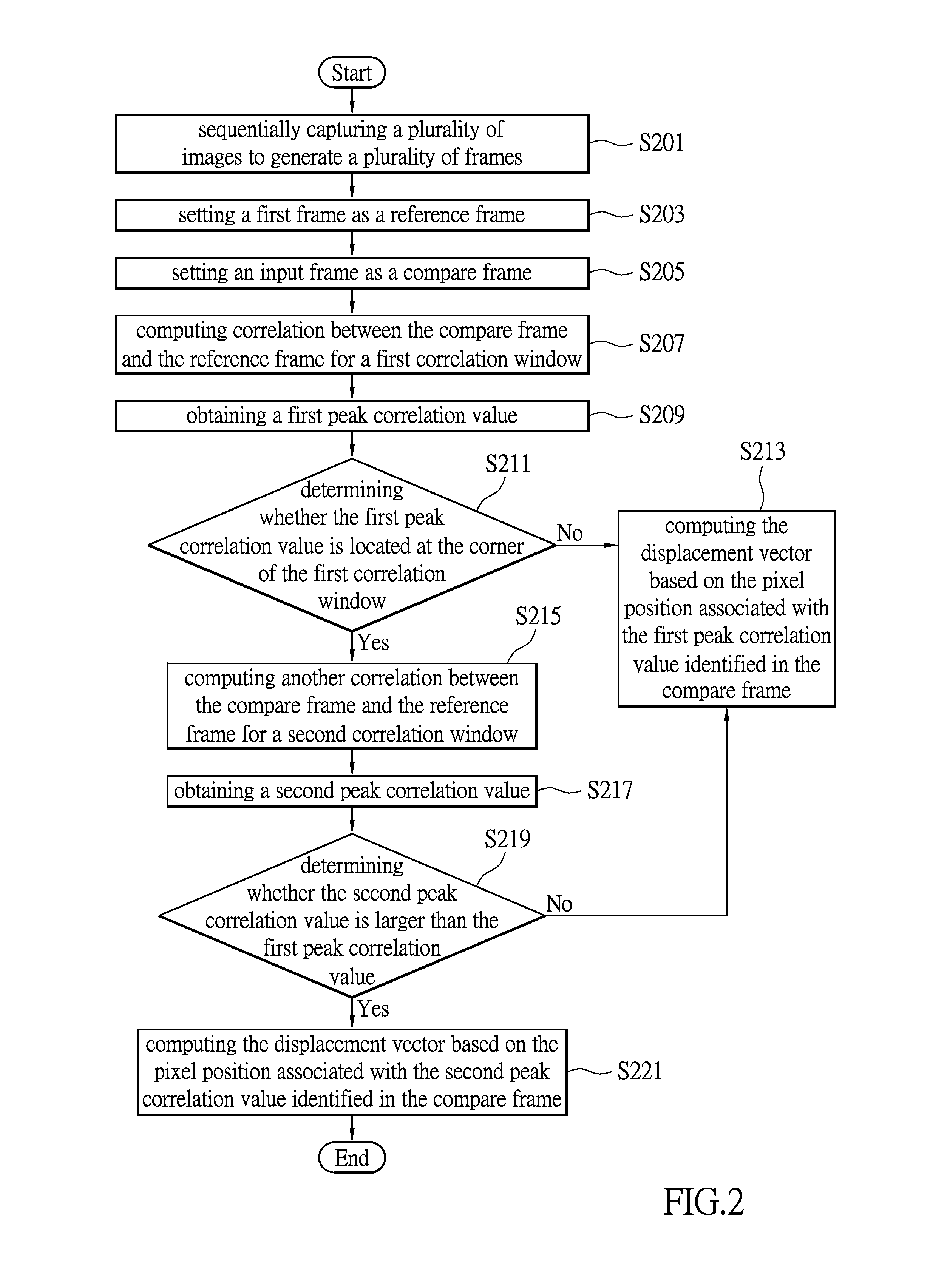
[0021]The objective of the present disclosure is to provide a tracking method, which can efficiently and accurately compute the displacement of an optical input device, such as an optical mouse, a joystick, and the like, through actively verifying the validity of the peak correlation value obtained from correlations between successive frames captured. Such that the optical input device is operable for precisely controlling the operation of a cursor on a display.

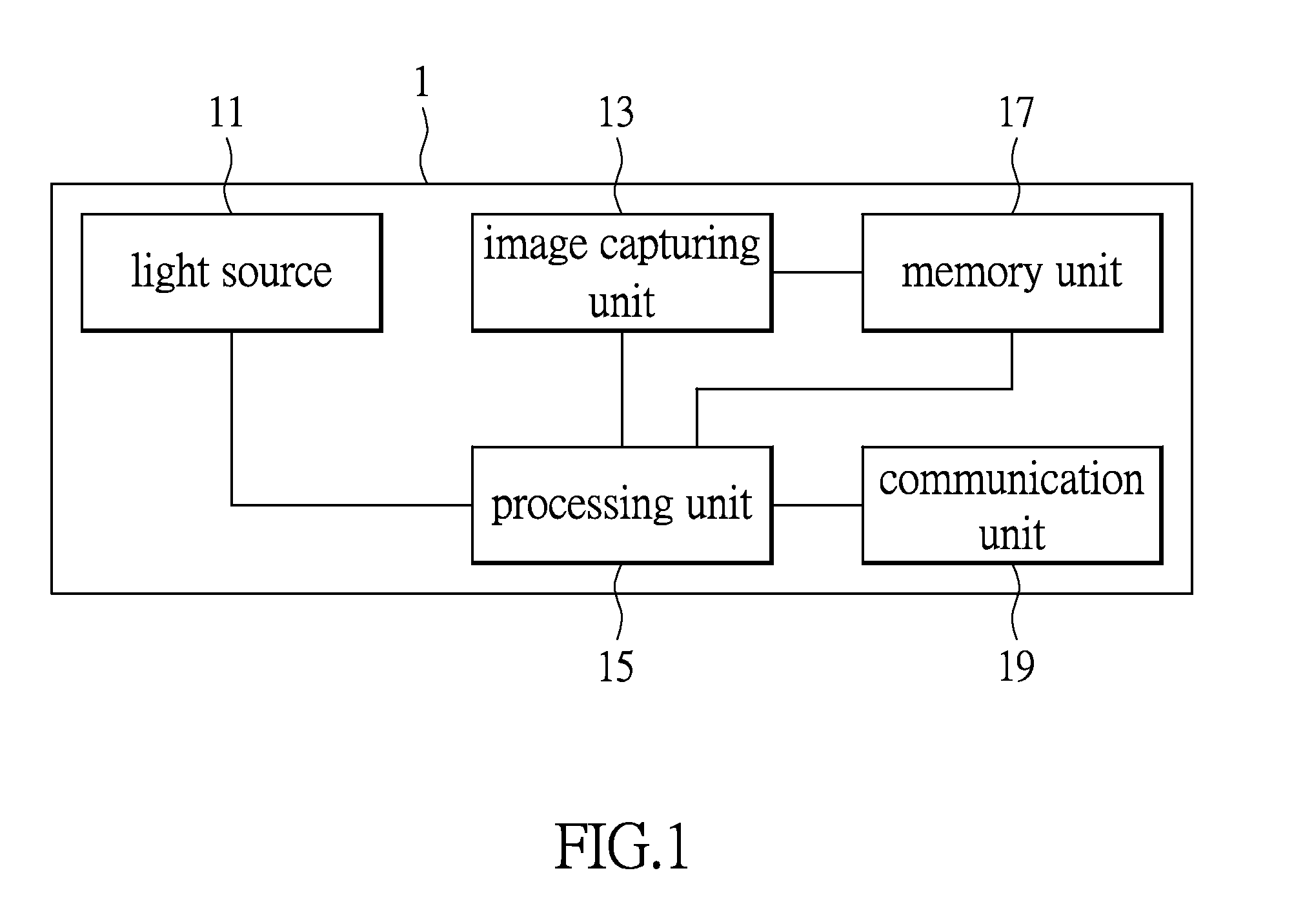
[0022]Information regarding the hardware architecture of the optical input device, the basic operations of the optical input device including capturing image, image processing, displacement computation, cursor control operation, are commonly ...


PUM


Abstract

A tracking method of an optical input device includes: capturing a first image as a reference frame and an input image subsequent to the first image as a compare frame while the optical input device operates; computing correlation between the compare frame and the reference frame for a first correlation window to obtain a first peak correlation value; computing another correlation between the compare frame and the reference frame for a second correlation window when the first peak correlation value identified is located at a corner of the first correlation window; when a second peak correlation value of the second correlation window is determined to be greater than the first peak correlation value, computes a displacement information of the optical input device based on the pixel position associated with the second peak correlation value identified in the compare frame.

Description

BACKGROUND[0001]1. Technical Field[0002]The present disclosure relates to an optical input device, in particular, to a tracking method of an optical input device and an optical input device using the same.[0003]2. Description of Related Art[0004]Correlation technique has been commonly used by optical input devices such as optical mice for aligning similar features between successive images captured i.e., a reference image and an input image (e.g., a compare image) captured subsequent to the reference image, so as to determine the relative motion (e.g., relative displacement and relative velocity) of the optical input device with respect to a work surface. The relative displacement and velocity tracked can be used for controlling the movement of a cursor on a display.[0005]One of the conventional correlation techniques is to correlate the reference image and the compare image on a pixel by pixel basis using a two-dimensional cross-correlation. Even though the pixel by pixel correlati...

Claims


Application Information

Patent Timeline
Patent Type & Authority Patents(United States)
IPC IPC(8): G06F3/038G06F3/03G06F3/0354
CPCG06F3/0383G06F3/0317G06F3/03543
Inventor LYE, KENG YEEN
Owner PIXART IMAGING INC
Why Eureka
Try Eureka