Set top box security tracking

a technology for security tracking and set top boxes, applied in the field of electric, electronic and computer arts, can solve the problems of unauthorized relocation of cpe devices, network configuration, and operators of broadband networks, and achieve the effect of efficient and accurate identification of inappropriately located cp

Active Publication Date: 2020-03-24
CHARTER COMM OPERATING LLC
View PDF16 Cites 0 Cited by
  • Summary
  • Abstract
  • Description
  • Claims
  • Application Information

AI Technical Summary

Benefits of technology

[0013]Techniques of the present invention can provide substantial beneficial technical effects. For example, one or more embodiments provide the ability to more efficiently and accurately identify inappropriately located CPE in broadband networks and the like.

Problems solved by technology

One significant issue for a cable operator desiring to provide digital service is the configuration of its network.
One issue of concern to the operators of broadband networks is the unauthorized relocation of CPE devices (e.g., “cable boxes,”“set-top boxes” or STBs).
For example, an unscrupulous individual might make unauthorized use of a STB.

Method used


Image

  • Set top box security tracking
  • Set top box security tracking
  • Set top box security tracking

Examples


Embodiment Construction

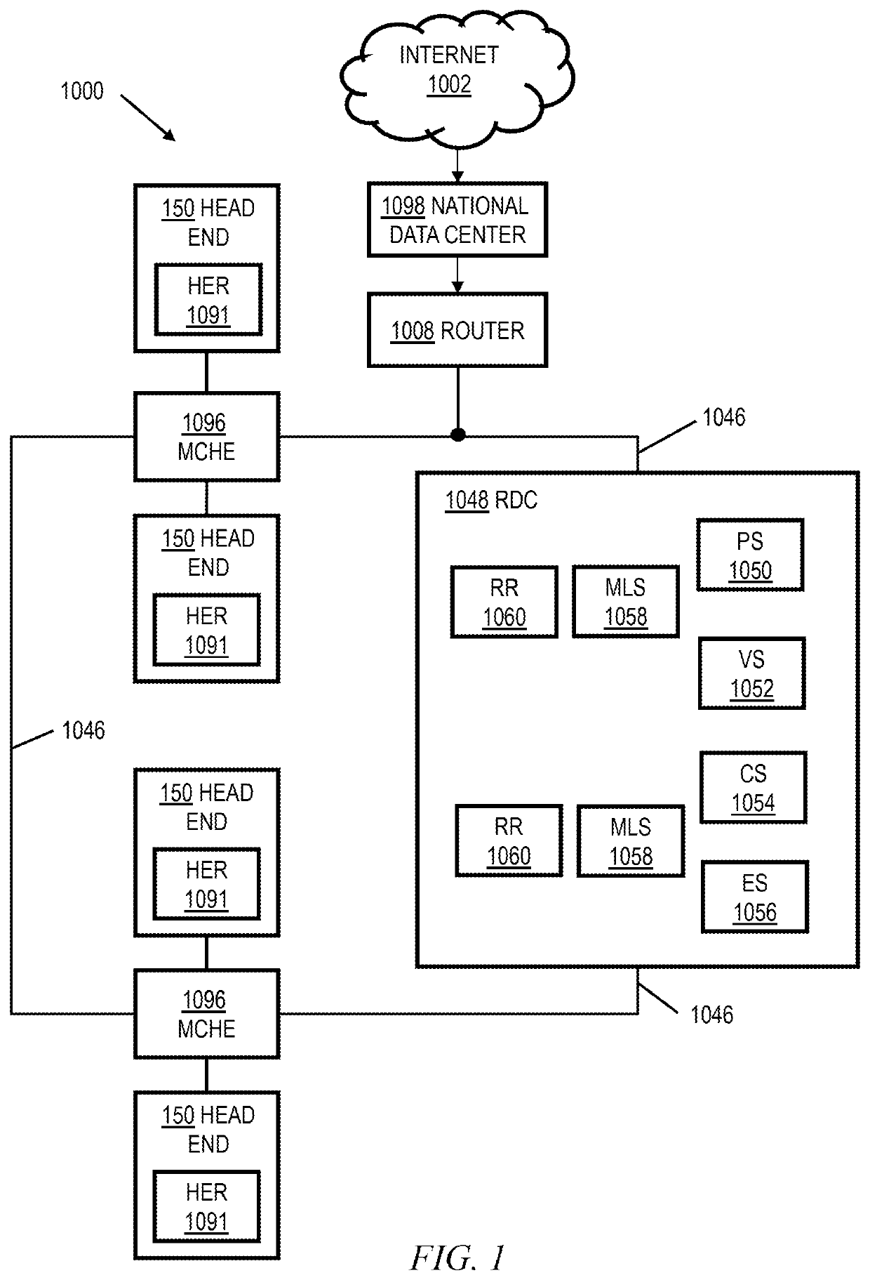
[0027]Purely by way of example and not limitation, some embodiments will be shown in the context of a cable multi-service operator (MSO) providing data services as well as entertainment services. FIG. 1 shows an exemplary system 1000, according to an aspect of the invention. System 1000 includes a regional data center (RDC) 1048 coupled to several Market Center Head Ends (MCHEs) 1096; each MCHE 1096 is in turn coupled to one or more divisions, represented by division head ends 150. In a non-limiting example, the MCHEs are coupled to the RDC 1048 via a network of switches and routers. One suitable example of network 1046 is a dense wavelength division multiplex (DWDM) network. The MCHEs can be employed, for example, for large metropolitan area(s). In addition, the MCHE is connected to localized HEs 150 via high-speed routers 1091 (“HER”=head end router) and a suitable network, which could, for example, also utilize DWDM technology. Elements 1048, 1096 on network 1046 may be operated,...


PUM


Abstract

A plurality of customer premises equipment devices in a broadband network are periodically polled to determine a corresponding upstream interface port for each of the plurality of customer premises equipment devices. The determined corresponding upstream interface ports for each of the plurality of customer premises equipment devices are compared to stored data indicating authorized upstream interface ports for each of the plurality of customer premises equipment devices. Responsive to the comparing indicating that at least one of the determined corresponding upstream interface ports does not match a corresponding one of the authorized upstream interface ports, at least one remedial action is taken for a customer account associated with a corresponding one of the customer premises equipment devices in the broadband network.

Description

FIELD OF THE INVENTION[0001]The present invention relates generally to the electrical, electronic, and computer arts, and more particularly relates to security tracking of set top boxes and other customer premises equipment (CPE) in broadband networks and the like.BACKGROUND OF THE INVENTION[0002]Cable television is a system of delivering television programming to paying subscribers via radio frequency (RF) signals transmitted through coaxial cables, or in more recent systems, light pulses through fiber-optic cables. Historically, the cable network was predominantly a vehicle for delivering entertainment. With the advent of the Internet and the rise in demand for broadband two-way access, the cable industry began to seek new ways of utilizing its existing plant. Pure coaxial (“coax”) cable networks were replaced with hybrid fiber / coax networks (HFCs) using optical fiber from the head end to the demarcation with the subscriber coax (usually at a fiber node). Currently, a content-base...

Claims


Application Information

Patent Timeline
Patent Type & Authority Patents(United States)
IPC IPC(8): H04N21/442H04N17/00
CPCH04N21/44209H04N17/004H04N21/44245H04N7/17309H04N21/2405H04N21/6118
Inventor GUTTERMAN, JEFFCREWS, RYAN
Owner CHARTER COMM OPERATING LLC
Why Eureka
Try Eureka