Self-centering braced frame for seismic resistance in buildings

a self-centering brace and building technology, applied in the direction of girders, joists, trusses, etc., can solve the problems of red tag, complete collapse, loss of use,

Active Publication Date: 2017-03-14
SIMPSON STRONG TIE
View PDF49 Cites 8 Cited by
  • Summary
  • Abstract
  • Description
  • Claims
  • Application Information

AI Technical Summary

Benefits of technology

The present invention provides an elongated tension-only brace for use in a building that can connect two structural members with a beam and a post. The brace has elastic restoring force elements that act to bring the two members back to their original position when the brace is subjected to external lateral loading. The brace can be designed to have a minimum effective length when not subjected to external loads, but can still expand and return to its original position when the brace is subjected to lateral loading. The brace is made up of a short brace member and an elongated brace member that are connected by one or more elastic restoring force elements. The elastic restoring force elements can be cables or other elastic elements that are fixed to the brace members. The brace can be designed to have a maximum length, and the elastic restoring force elements can be wound around additional pulleys to increase the effective length of the brace. The technical effect of this invention is to provide a centering brace that can connect two structural members with a beam and a post, and can automatically return to its original position when the brace is subjected to external loads.

Problems solved by technology

At best this can lead to loss of use (red tag) and at worst complete collapse in subsequent aftershocks.
For this to happen the pre-stressed element must remain elastic (unyielding) even as it is stretched under the combined demands of the pre-stressing and the supplemental strain induced by building deformations during an earthquake, and it is in meeting these combined strain demands by stretching without yielding that many of the difficulties of designing such systems are encountered.
One of the challenges of self-centering systems is configuring the geometry of the building and the self-centering system in such a way that the strain induced in the elastic restoring force elements that provide the force necessary to pull the building back to its original position (this is called the “restoring force”) does not exceed the yield strain for the materials from which the elastic force restoring elements are made.
One researcher, Alan Jamal Stewart, has found that tendon yielding and loss of elasticity can still be a problem with moment-resisting frames designed with gap opening behavior at the beam-column joints.
Self-centering moment frame systems that rely on the gap-opening behavior of beam-to-column joints to dissipate energy also have a problem in their design that may interfere with their adoption.
While initially this was considered an academic problem in that it was mostly theoretical, the Feb. 22, 2011, Christchurch, New Zealand earthquake has now provided real-world examples of why this is a problem.
Self-centering systems that rely on high aspect ratio rocking frames also create a unique set of problems in addition to the possible yielding of the restoring force elements mentioned above with respect to moment resistant frames that rely on gap opening.
However, perhaps the biggest challenge with rocking self-centering frames is designing the interface with the surrounding structure.
Conventional bracing geometry typically does not work because the axial strain demands (stretch) imposed on the braces would be too large to accommodate without yielding; however, the benefits to this approach is that the frame no longer has to rock, avoiding the associated problems of rocking frames, and the beam-column joints do not have to allow for gap opening as described above in the self-centering moment frame system.
In order for steel member that is 206 inches in length to stretch 1.8 inches without yielding, the yield stress of the steel would have to be at least 253,400 psi, which is not feasible.

Method used


Image

  • Self-centering braced frame for seismic resistance in buildings
  • Self-centering braced frame for seismic resistance in buildings
  • Self-centering braced frame for seismic resistance in buildings

Examples


Embodiment Construction

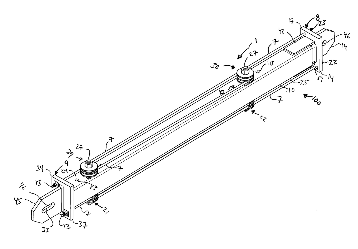
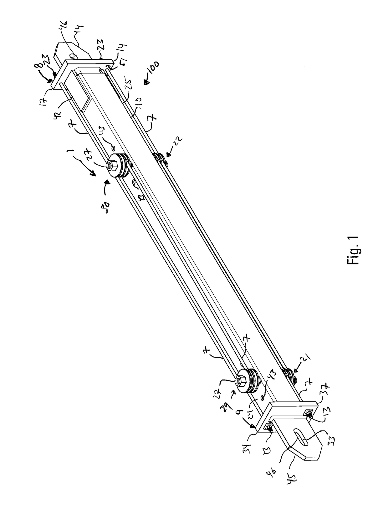
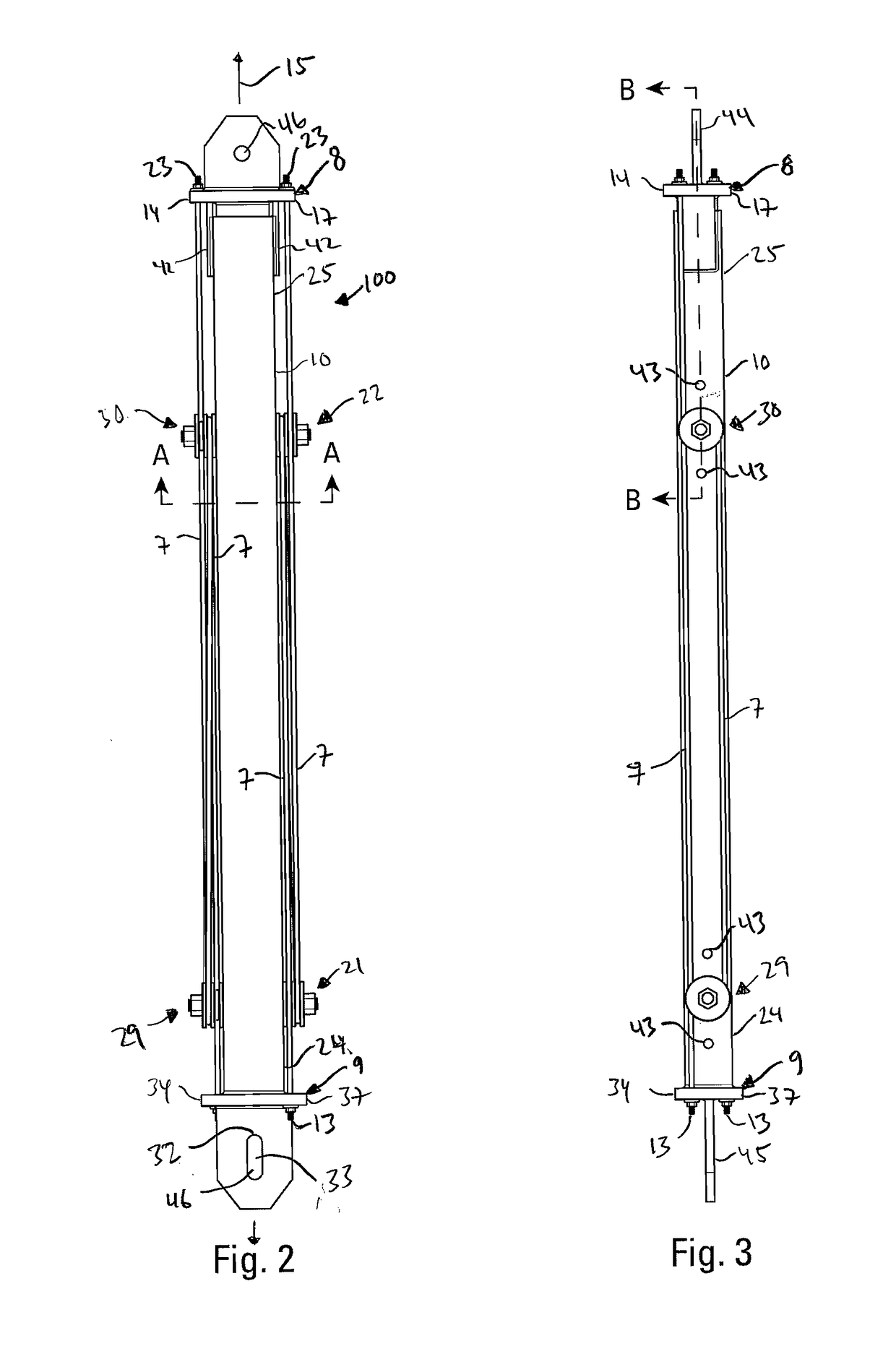
[0040]The present invention provides an elongated, tension-only or centering brace 1 in a frame 2 for a structure, such as a building, where the brace is anchored at a first attachment point 3, typically, the first attachment point would be along an upstanding post or column 4, and where the brace is anchored at a second attachment point 5 that is removed from the first attachment point 3, typically at a point somewhere along a beam 6. The elongated tension-only brace has one or more elastic restoring force elements 7 that have effective lengths greater than the distance between the first and second attachment points, where the brace 1 is anchored. The effective lengths of the elastic restoring force elements are long enough such that they do not stretch beyond their yield points under selected design loads, such as those caused by an earthquake. Typically the vertical columns and horizontal beams of the frame that would use such a brace would be made from steel “W” sections which h...


PUM


Abstract

An elongated tension-only or centering brace for a structural frame is provided where the brace is anchored at a first attachment point and to a second attachment point that is removed from the first attachment point. The elongated tension-only brace has one or more elastic restoring force elements that have effective lengths greater than the length of the tension only brace between the attachment points.

Description

BACKGROUND OF THE INVENTION[0001]The present invention provides a self-centering system for the structural frame of a building, in particular, the present invention provides a tension brace that provides elastic restoring forces to the frame of the building.[0002]After an earthquake, permanent damage in even properly designed structures may allow for a building to come to rest in an out-of-plumb condition, which is often referred to as “residual (horizontal) displacement”. At best this can lead to loss of use (red tag) and at worst complete collapse in subsequent aftershocks. In recent years state-of-the-art earthquake resistant design research has focused on systems that are capable of ensuring that after an earthquake a building would have little, if any, residual displacement, thus they are “self-centering”. The proposed invention is such a system.[0003]Various types of self-centering systems have been proposed. Inherent in the self-centering philosophy is the need for something ...

Claims


Application Information

Patent Timeline
Patent Type & Authority Patents(United States)
IPC IPC(8): E04H9/02E04C3/04E04B1/24E04C3/02
CPCE04H9/021E04B1/24E04C3/04E04B2001/2496E04C2003/026E04C2003/0413E04H9/028E04H9/0237
Inventor PRYOR, STEVEN E.
Owner SIMPSON STRONG TIE
Why Eureka
Try Eureka