Supercharge Your Innovation With Domain-Expert AI Agents!

Arrangement of a segmented retractable seal in a stator of a turbine

a turbine and retractable seal technology, which is applied in the direction of engine seals, leakage prevention, liquid fuel engine components, etc., can solve the problems of blocking the movement of the rotor seal, affecting the utilization of several such rotor seals, and affecting the efficiency of the operation

Active Publication Date: 2017-03-21
DOOSAN SKODA POWER
View PDF10 Cites 3 Cited by
  • Summary
  • Abstract
  • Description
  • Claims
  • Application Information

AI Technical Summary

Benefits of technology

The invention describes a new arrangement of a retractable rotor seal in a turbine that solves the problem of previous arrangements. The new arrangement uses a groove in the stator and a seal head and comb that move radially and axially in the groove. The seal is connected with a neck and has a minimum clearance with the stator wall. This arrangement creates a sealing point that reduces friction forces and increases the pressing force, making the movement of the seal more reliable than previous arrangements. The movement of the seal is limited by back stops, and the arrangement includes a step or protrusion on the lower surface of the seal head or on its side.

Problems solved by technology

However, their disadavantage is the fact that the pressure of the sealed medium does not always create force necessary to overcome the force of retractring springs, weight of the rotor seal itself and friction forces in the duct, and thus to press the rotor seal to the operating position.
This is caused mainly by the fact that the friction forces, which are relatively hard to predict, can moreover change in course of time, for instance as a result of sedimentation of impurities, and can even completely block the movement of the rotor seal.
In pursuit of solving these negative effects, the construction of rotor seals generally becomes very demanding as to the mounting—see for example EP 2048366, where the rotor seal has large dimensions, while the width of its head exceeds the widthof its sealing comb, which complicates or totally disables utilization of several such rotor seals arranged in a row next to each other.

Method used


Image

  • Arrangement of a segmented retractable seal in a stator of a turbine
  • Arrangement of a segmented retractable seal in a stator of a turbine
  • Arrangement of a segmented retractable seal in a stator of a turbine

Examples


embodiment

OF EMBODIMENT

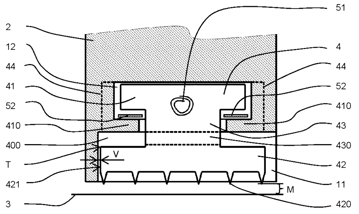
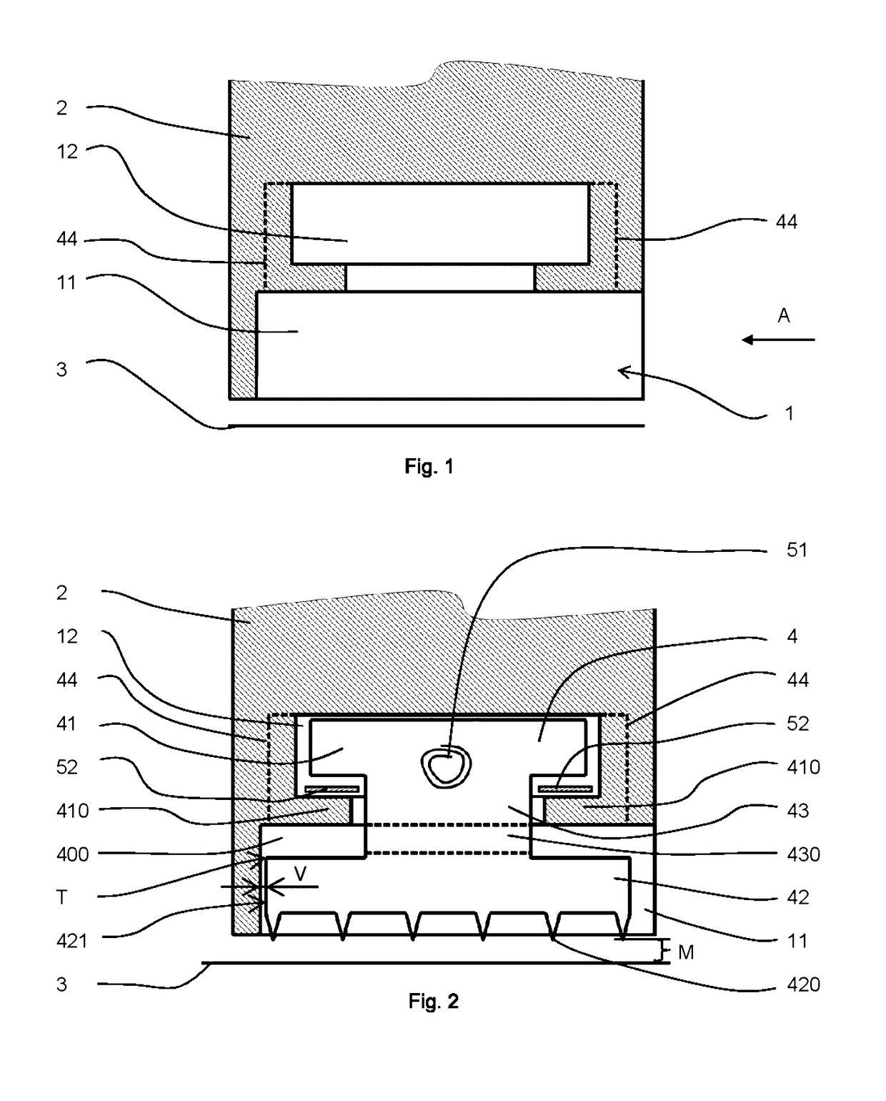
[0015]The arrangement of segmented retractable rotor seal according to the invention is based, as well as in the case of the same types of rotor seals known from the prior art, on the fact that the seal is arranged in a groove formed in a stator of a turbine along the whole circumference of the stator. The groove 1—see FIG. 1, in the embodiment according to the invention consists of an outer partial groove 11 with rectangular cross section formed on the inner surface of the stator 2, the groove being opened in the direction away from the rotor 3 and in the direction of the flow of the sealed medium (arrow A), to which is connected inner partial groove 12 having rectangular cross section, which is formed in the stator body 2 and which is closed from all sides, with the exception of its connection with the outer partial groove 11. The width of the inner partial groove 12 is advantageously smaller than that of the outer partial groove 11, as can be seen in the represented ...


PUM


Abstract

A segmented retractable seal is provided in a stator of a turbine by which a rotor seal is arranged radially and axially movably in a groove formed in the stator of the turbine and is connected with a mechanism which retracts it away from the rotor of the turbine in a radial direction. The groove formed in the stator of the turbine contains an outer partial groove formed on the inner surface of the stator and an inner partial groove formed in the body of the stator and connected with it, its width being smaller than or equal to that of the outer partial groove. A head of the seal is arranged in the inner partial groove, and a comb of the seal is arranged in the outer partial groove. The head of the seal and the comb of the seal are connected by a neck of the seal.

Description

TECHNICAL FIELD[0001]The invention relates to an arrangement of a segmented retractable seal in a stator of a turbine, in which the seal is arranged radially and axially movably in a groove formed in the stator of the turbine and is connected with a means which retracts it away from the turbine rotor in radial direction.BACKGROUND ART[0002]For mutual sealing of pressurized and underpressure spaces of a turbine and for sealing them against atmospheric pressure numerous different types of rotor seals are currently used, as well as methods of their arrangement. In order to avoid mechanic damage of the turbine due to increasing vibrations when the turbine passes the critical speed of the rotor, for example during the start-up of the rotor—seals are always designed with the minimum posssible gap between the rotor and the stator—above all movable (retractable) rotor seals are used, whereby during the turbine start-up the movable (retractable) seals are distanced from the rotor and approac...

Claims


Application Information

Patent Timeline
Patent Type & Authority Patents(United States)
IPC IPC(8): F01D11/12F16J15/44F01D11/00F01D11/02F04D29/10
CPCF01D11/12F01D11/001F01D11/025F16J15/442F04D29/102
Inventor HASNEDL, DANPRCHLIK, LUBOS
Owner DOOSAN SKODA POWER
Features
  • R&D
  • Intellectual Property
  • Life Sciences
  • Materials
  • Tech Scout
  • Unparalleled Data Quality
  • Higher Quality Content
  • 60% Fewer Hallucinations
Learn More