Sealed rolling bearing

a rolling bearing and seal technology, applied in the direction of bearing components, shafts and bearings, engine seals, etc., can solve the problems of large width and difficulty in assembly, less use of mounted seals, and inability to mount the axial lips with required, so as to improve the durability and wear resistance, prevent the effect of foreign matter entry

Active Publication Date: 2017-03-21
NTN CORP
View PDF25 Cites 1 Cited by
  • Summary
  • Abstract
  • Description
  • Claims
  • Application Information

AI Technical Summary

Benefits of technology

[0011]Since the first and second radial lips provided on the sealing member of each sealing device are in elastic contact with the cylindrical seal slide-contact surface formed on the outer periphery of the cylindrical portion of the slinger, the sealing device provides a double seal. Thus the sealing device can effectively prevent entry of foreign matter such as muddy water. Also, this bearing is narrower in width than the bearing with two seal members arranged axially parallel to each other on each side of the bearing space to seal the bearing space.
[0012]A support bearing for an intermediate shaft through which torque is applied to a constant-velocity joint usually has a bearing axial play (which allows axial movement of the bearing parts) of less than 0.3 mm at the most. Thus, for each of the sealing devices, an axial gap of 0.3 to 0.5 mm is preferably defined between the distal end of the outer one of the first and second radial lips and the inner side surface of the annular portion of the slinger such that even if the seal member and the slinger are moved relative to each other by the distance equal to the above bearing axial play, the outer one of the first and second radial lips never abuts at its distal end the inner side surface of the annular portion of the slinger. This prevents damage to the radial lip.
[0013]For each of the sealing devices, by providing the annular portion of the slinger with an inwardly bent portion, and a disk portion extending from the outer periphery of the inwardly bent portion, substantially parallel to the annular portion of the sealing member, thereby defining a labyrinth gap between the disk portion and the annular portion of the sealing member, it is possible to prevent entry of foreign matter between the opposed portions of the slinger and the seal member. Even if foreign matter should enter between the opposed portions, such foreign matter can be discharged radially outwardly under the centrifugal force generated when the slinger rotates. Thus, this arrangement prevents foreign matter from sticking to or being deposited on the seal slide-contact surface, thus deteriorating sealability.
[0014]For each of the sealing devices, by providing the annular portion of the slinger with an outwardly bent portion formed by axially outwardly bending a part of the annular portion of the slinger extending from the outer periphery of the disk portion such that a minute gap is defined between the outwardly bent portion and the inner peripheral surface of the cylindrical portion of the seal member, the rotating outwardly bent portion can throws off flying foreign matter such as muddy water. The minute gap, as a labyrinth, further effectively prevents entry of foreign matter into the interior of the sealing device.
[0017]For improved durability against corrosion, the slinger is preferably formed of a stainless steel plate or a molten zinc-plated steel plate. Each of the first radial lip and the second radial lip is preferably made of a synthetic rubber that is high in wear resistance, such as nitrile rubber, acrylic rubber and fluororubber.
[0018]According to the present invention, for each of the sealing devices, since the first radial lips and the second radial lips of the sealing member are in elastic contact with the cylindrical seal slide-contact surface formed on the outer periphery of the cylindrical portion of the slinger, providing a double seal, it is possible to effectively prevent entry of foreign matter such as muddy water, while minimizing the width of the bearing.

Problems solved by technology

However, externally mounted seals are less used in today's support bearings of this type for reduced weight, fuel consumption and cost, and internally mounted seals are used instead to prevent entry of foreign matter such as muddy water.
The sealed rolling bearing disclosed in either of Patent documents 1 and 2 is large in width and difficult to assemble, because this bearing includes a total of four contact seals, with two of them on each side of the bearing, and these four contact seals have to be mounted in position by press fitting.
On the other hand, the sealed rolling bearing including the sealing devices disclosed in Patent document 3 has a problem in that due to an axial play of the bearing that allow axial relative movement of the bearing parts, as well as misalignment during assembling, it is impossible to mount the axial lips with required interference, which makes it difficult to ensure sealability of the sealing devices.

Method used


Image

  • Sealed rolling bearing
  • Sealed rolling bearing
  • Sealed rolling bearing

Examples


Embodiment Construction

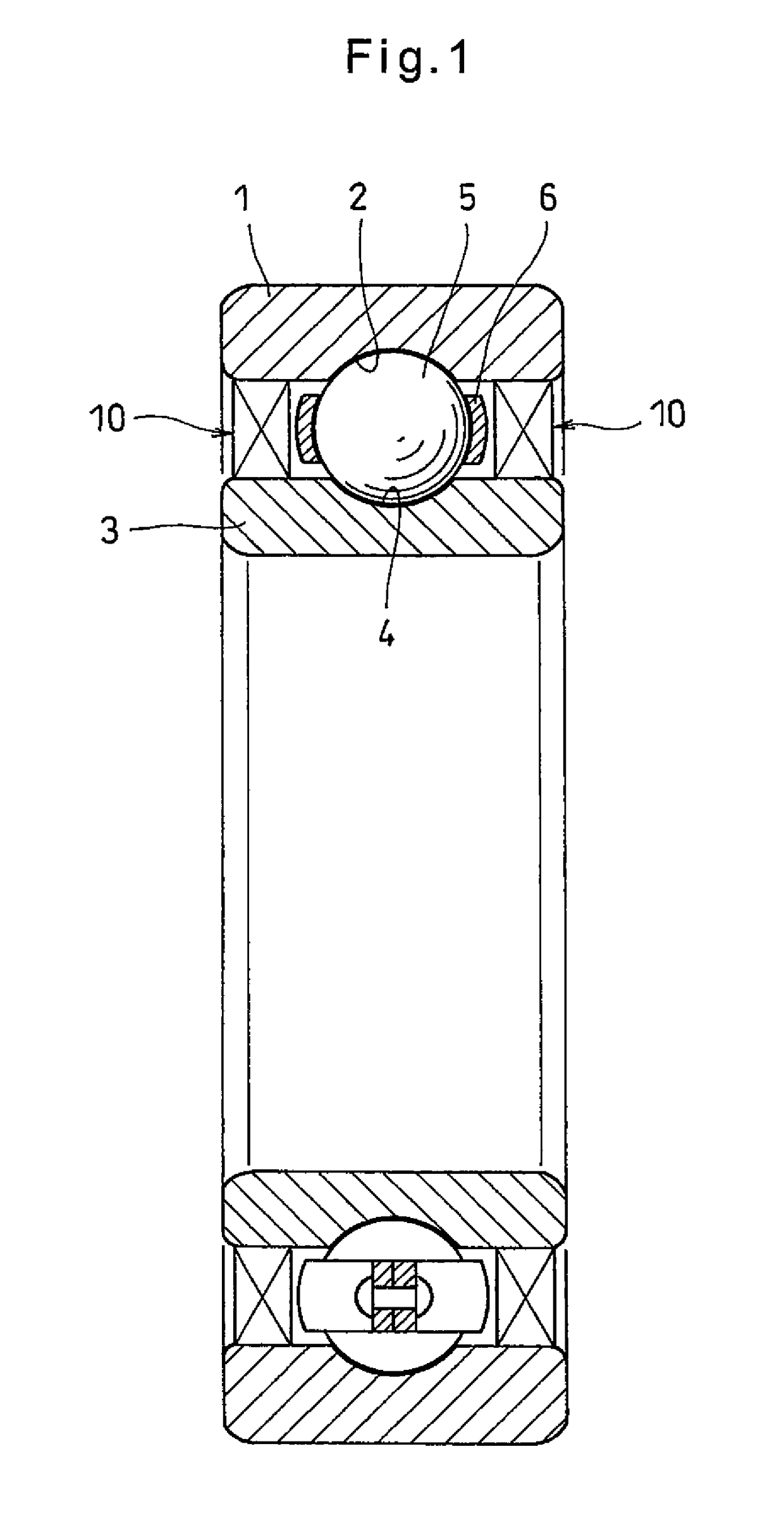
[0022]Now an embodiment of the present invention is described with reference to the drawings. As shown in FIG. 1, the rolling bearing of the embodiment includes an outer race 1 formed with a ball groove 2 in its radially inner surface, and an inner race 3 mounted inside the outer race 1 and formed with a ball groove 4 formed in the radially outer surface thereof. The rolling bearing further includes balls 5, as rolling elements, mounted between the ball groove 2 of the outer race 1 and the ball groove 4 of the inner race 3, and retained by a retainer 6.

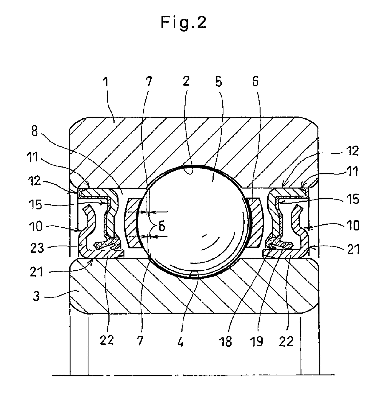
[0023]As shown in FIG. 2, the ball groove 2 of the outer race 1 and the ball groove 4 of the inner race 3 have radii of curvature larger than the radii of the balls 5 such that axial gaps 7 form between each ball 5 and the respective ball grooves 2 and 4. The axial gaps 7 allow relative axial movement between the outer race 1 and the inner race 3 by a distance δ, which is usually less than 0.3 mm if the bearing is a support bearing su...


PUM


Abstract

A sealed rolling bearing includes an outer race and an inner race. A cylindrical portion provided at the outer portion of a sealing member is press-fitted into each end of the outer race. A cylindrical portion provided at the inner portion of a slinger is press-fitted onto each end of the inner race. The sealing member has at its inner peripheral portion first and second radial lips which are in elastic contact with the slinger to prevent entry of foreign matter into the bearing space. The slinger has an annular portion including an axially outwardly extending, outwardly bent portion provided at its outer peripheral portion. The outwardly bent portion has an outer periphery located inwardly of the outer end of the cylindrical portion of the sealing member. A small gap is defined between the outwardly bent portion and the inner surface of the cylindrical portion as a labyrinth.

Description

TECHNICAL FIELD[0001]This invention relates to a sealed rolling bearing including sealing devices which close openings at the respective ends of the bearing space defined between the outer race and the inner race of the bearing.BACKGROUND ART[0002]A support bearing used for an intermediate shaft through which torque is applied to a constant-velocity joint coupled to a propeller shaft or a drive shaft of a motor vehicle is mounted under the vehicle floor and used under such harsh conditions that small stones and muddy water fly. Thus, old support bearings of this type were provided with externally mounted seals to prevent entry of foreign matter.[0003]However, externally mounted seals are less used in today's support bearings of this type for reduced weight, fuel consumption and cost, and internally mounted seals are used instead to prevent entry of foreign matter such as muddy water. Such internally mounted seals may comprise two pairs of contact seals, each pair being arranged axia...

Claims


Application Information

Patent Timeline
Patent Type & Authority Patents(United States)
IPC IPC(8): F16C33/76F16C33/78F16J15/32F16C33/80F16C19/06F16J15/3232F16J15/447
CPCF16C33/766F16C33/7883F16C33/805F16J15/3264F16C19/06F16C2326/06
Inventor TOMURA, YASUNARI
Owner NTN CORP
Why Eureka
Try Eureka