

Seal device for water pump, rotation supporting device for water pump and assembly method for water pump
a technology of water pump and supporting device, which is applied in the direction of machines/engines, liquid fuel engines, manufacturing tools, etc., can solve the problems of difficult to obtain a perfect seal, matter condensation, leakage, etc., and achieve the effect of preventing foreign matter entry, preventing foreign matter adhesion, and manufacturing stably
- Summary
- Abstract
- Description
- Claims
- Application Information
AI Technical Summary
Benefits of technology
Problems solved by technology
Method used
Image

Examples
Embodiment Construction
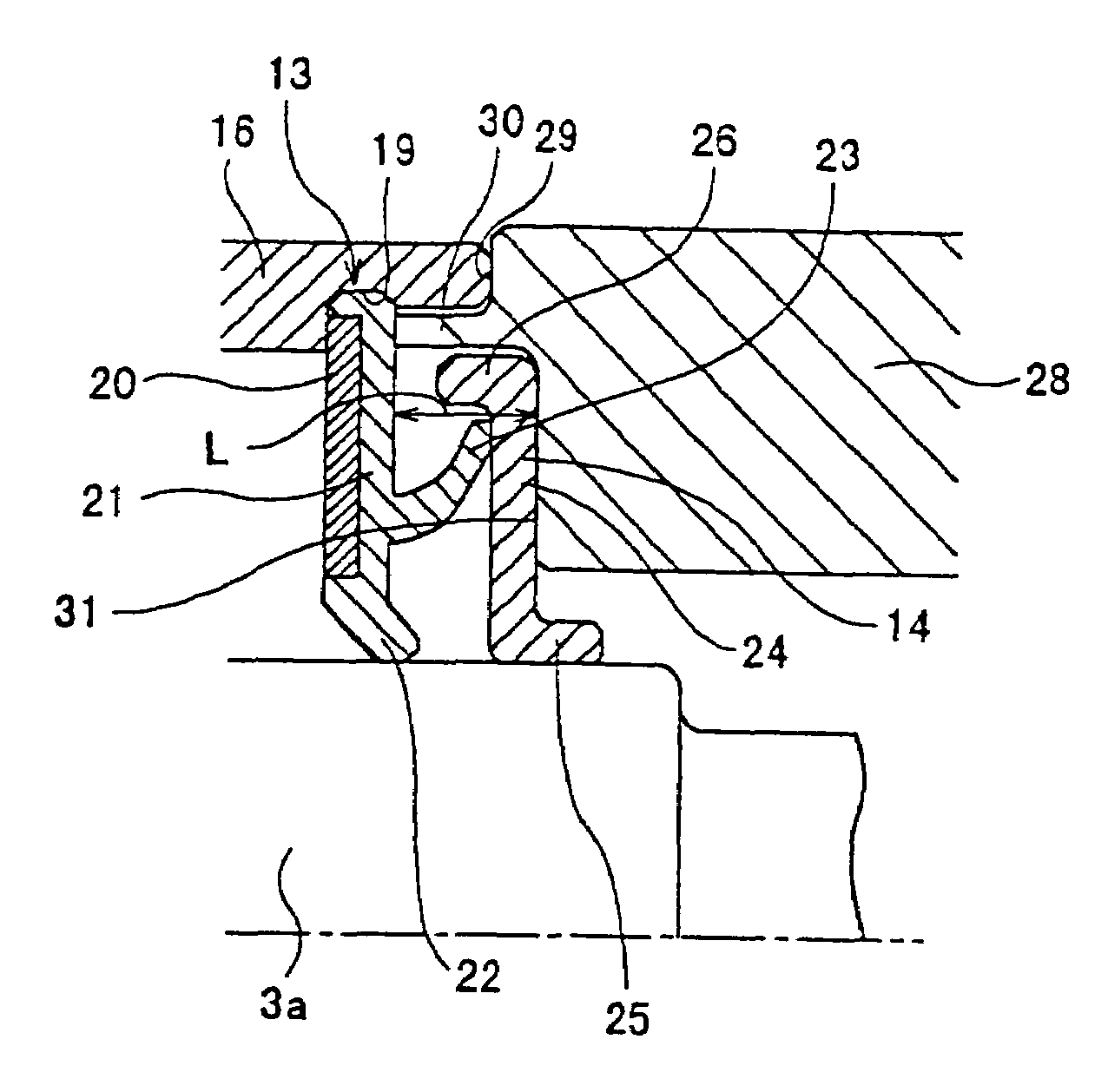
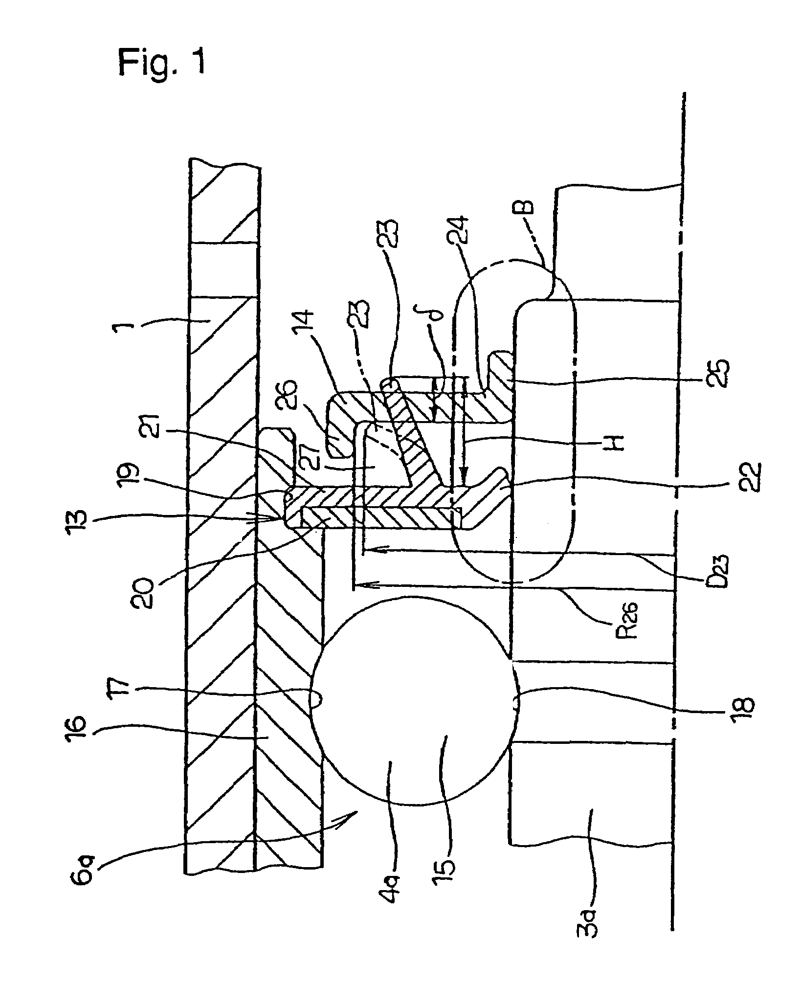
[0036]FIG. 1 shows a first example of the construction of a seal apparatus for a water pump covered by the method of assembly of the present invention. The characteristic of the seal apparatus for a water pump to which the method of assembly of this example is applied is that, by suitable regulation of the shape and dimensions of the seal ring 13 and slinger 14 provided in the middle section of the rotating shaft 3a further toward the outside than the mechanical seal 10 (see FIG. 10), it is difficult for steam or hot water passing through the mechanical seal 10 to enter the rolling bearing unit 6a including the plurality of rolling elements (balls) 15. Since the overall construction and the like of the water pump, and the construction and operation of other sections are substantially the same as for a conventional water pump, including the construction shown in FIG. 10, drawings and explanations of identical sections are omitted or simplified, and the explanation will concentrate on...
PUM
| Property | Measurement | Unit |
|---|---|---|
| height Ry | aaaaa | aaaaa |
| arithmetic mean roughness Ra | aaaaa | aaaaa |
| arithmetic mean roughness | aaaaa | aaaaa |
Abstract
Description
Claims
Application Information