
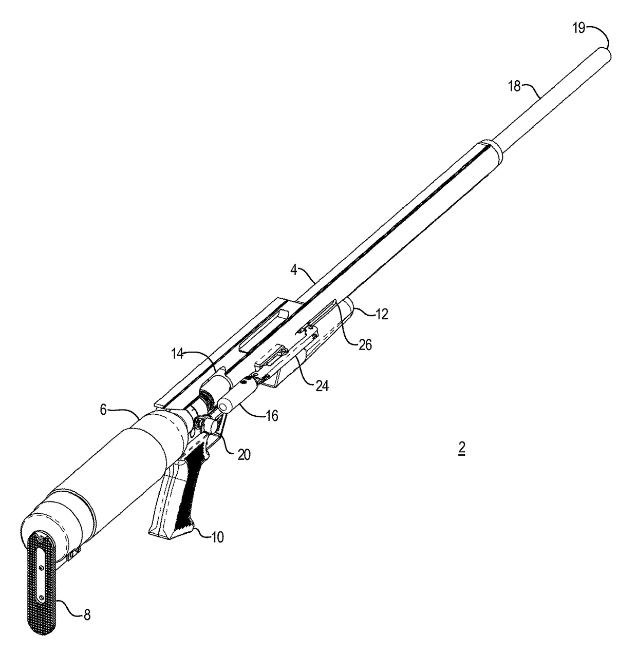
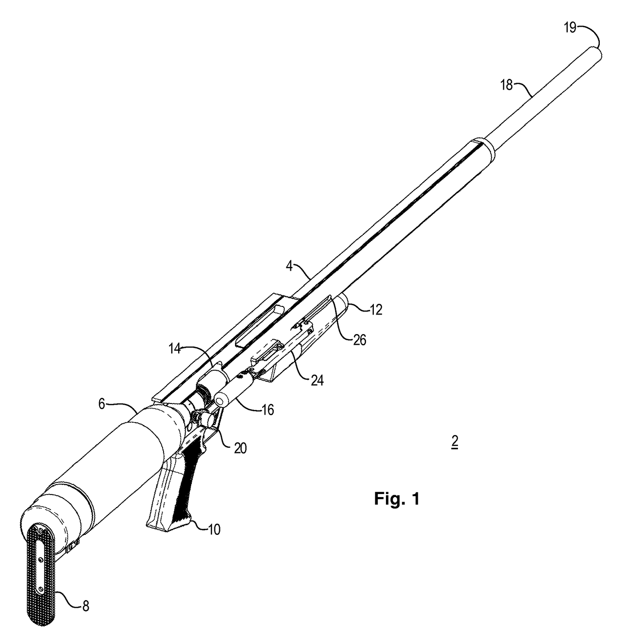
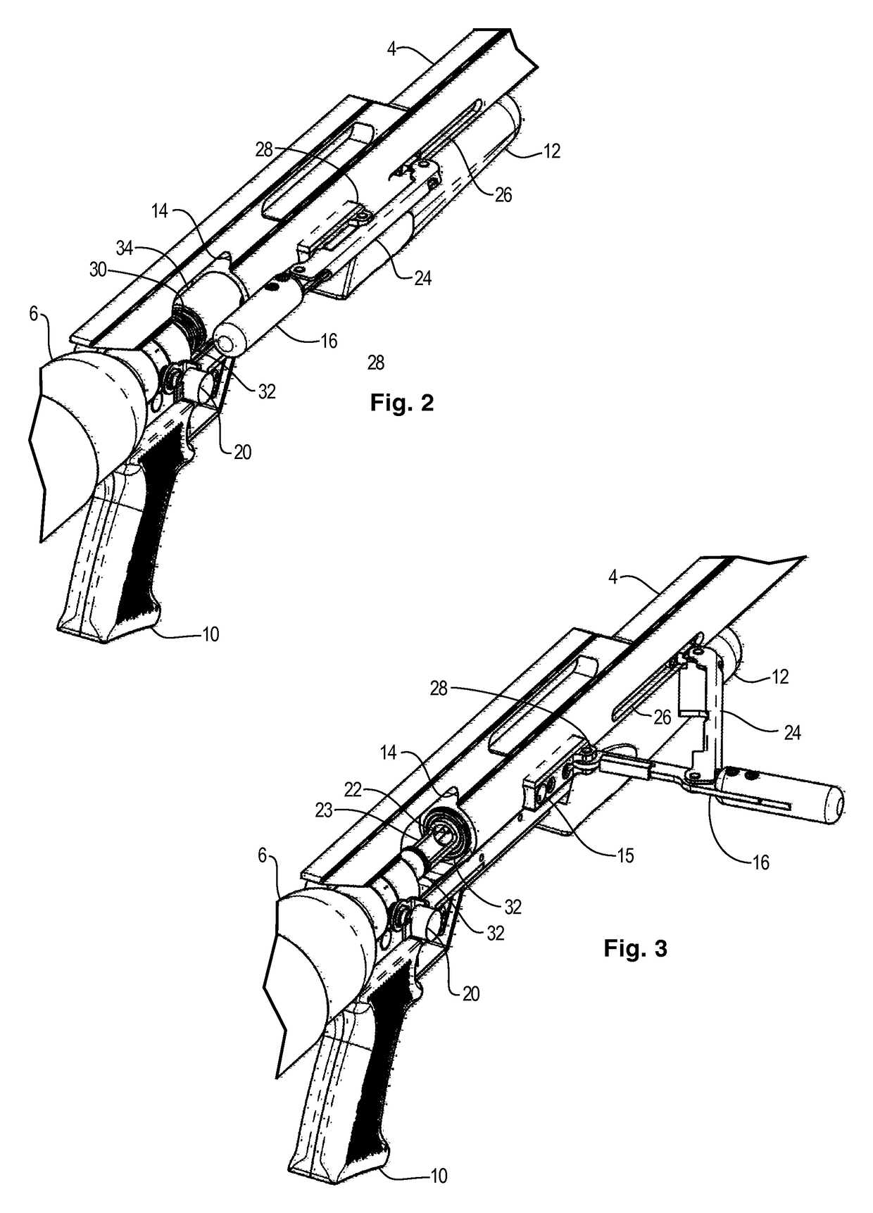
Compressed gas gun with improved operating mechanism

a gas gun and operating mechanism technology, applied in the field of compressed gas guns, can solve the problems of increasing the compressive force of the mainspring, the weight of the related, and the difficulty of operators applying cocking force, and achieve the effect of facilitating the insertion of the projectil

Active Publication Date: 2017-03-28
MCCASLIN JOHN A
View PDF17 Cites 11 Cited by
  • Summary
  • Abstract
  • Description
  • Claims
  • Application Information

AI Technical Summary

Benefits of technology

The patent describes an apparatus that has a spring stop position that can be adjusted. This allows for adjustment of the main spring's compression. The technical effect of this is that it provides a means for precise control and adjustment of the apparatus's spring compression, improving its reliability and performance.

Problems solved by technology

While the prior loading, cocking, and discharging mechanisms have performed well with lighter caliber guns, the higher forces required to discharge heavier calibers has correspondingly increased mainspring compressive forces, and the size and weight of related components, such that the operator applied cocking forces have become challenging for some operators.

Method used


Image

  • Compressed gas gun with improved operating mechanism
  • Compressed gas gun with improved operating mechanism
  • Compressed gas gun with improved operating mechanism

Examples


Embodiment Construction

[0036]Illustrative embodiments and exemplary applications will now be described with reference to the accompanying drawings to disclose the advantageous teachings of the present invention.

[0037]While the present invention is described herein with reference to illustrative embodiments for particular applications, it should be understood that the invention is not limited thereto. Those having ordinary skill in the art and access to the teachings provided herein will recognize additional modifications, applications, and embodiments within the scope hereof and additional fields in which the present invention would be of significant utility.

[0038]In considering the detailed embodiments of the present invention, it will be observed that the present invention resides primarily in combinations of steps to accomplish various methods or components to form various apparatus and systems. Accordingly, the apparatus and system components and method steps have been represented where appropriate by...


PUM


Abstract

A compressed gas gun with a cocking mechanism that provides a mechanical advantage in compressing a mainspring, while providing a two stage loading and cocking action that accesses and seals a breech through utilization of an intermediate cocking member.

Description

BACKGROUND OF THE INVENTION[0001]Field of the Invention[0002]The present invention relates to compressed gas guns. More particularly, the present invention relates to compressed gas guns that employ a cocking mechanism, which yields a mechanical advantage for the compression of a main spring.[0003]Description of the Related Art[0004]Compressed gas guns operate to release a quantity of compressed gas into the breech of a barrel, which has been pre-loaded with a projectile, thereby propelling the projectile out of the barrel at high velocity. In practice, such a gun must provide a source of compressed gas in order to function. Typically, this source of gas is an air tank that is pre-charged prior to being coupled with the gun, or a fixed tank that is charged in place while coupled to the gun. As such, these are referred to as pneumatic pre-charged (PCP) guns. In either case, the tank holds a finite quantity of compressed gas. Upon discharging the gun one or more times, the reserve of ...

Claims


Application Information

Patent Timeline
Patent Type & Authority Patents(United States)
IPC IPC(8): F41B11/70F41B11/723F41B11/62
CPCF41B11/70F41B11/62F41B11/723F41A3/72
Inventor MCCASLIN, JOHN A.
Owner MCCASLIN JOHN A
Learn More