Timepiece comprising a device indicating the power reserve

A technology of power reserve and timer, which is applied in the field of winding degree devices, can solve the problems of inadmissible reduction ratio and hindering the application of small-thickness movement, and achieve the effect of reducing space requirements

Active Publication Date: 2008-10-08
MONTRES BREGUET
View PDF2 Cites 10 Cited by
  • Summary
  • Abstract
  • Description
  • Claims
  • Application Information

AI Technical Summary

Problems solved by technology

However, the reduction ratio provided by this type of differential gear does not allow the display of the power reserve over a small arc, for example an arc of about 30°, without showing the reduction train
Furthermore, although this power reserve is compact in the horizontal direction, it has an extremely high space requirement in the height direction, which hinders its application in movements of small thickness

Method used


Image

  • Timepiece comprising a device indicating the power reserve
  • Timepiece comprising a device indicating the power reserve
  • Timepiece comprising a device indicating the power reserve

Examples


Embodiment Construction

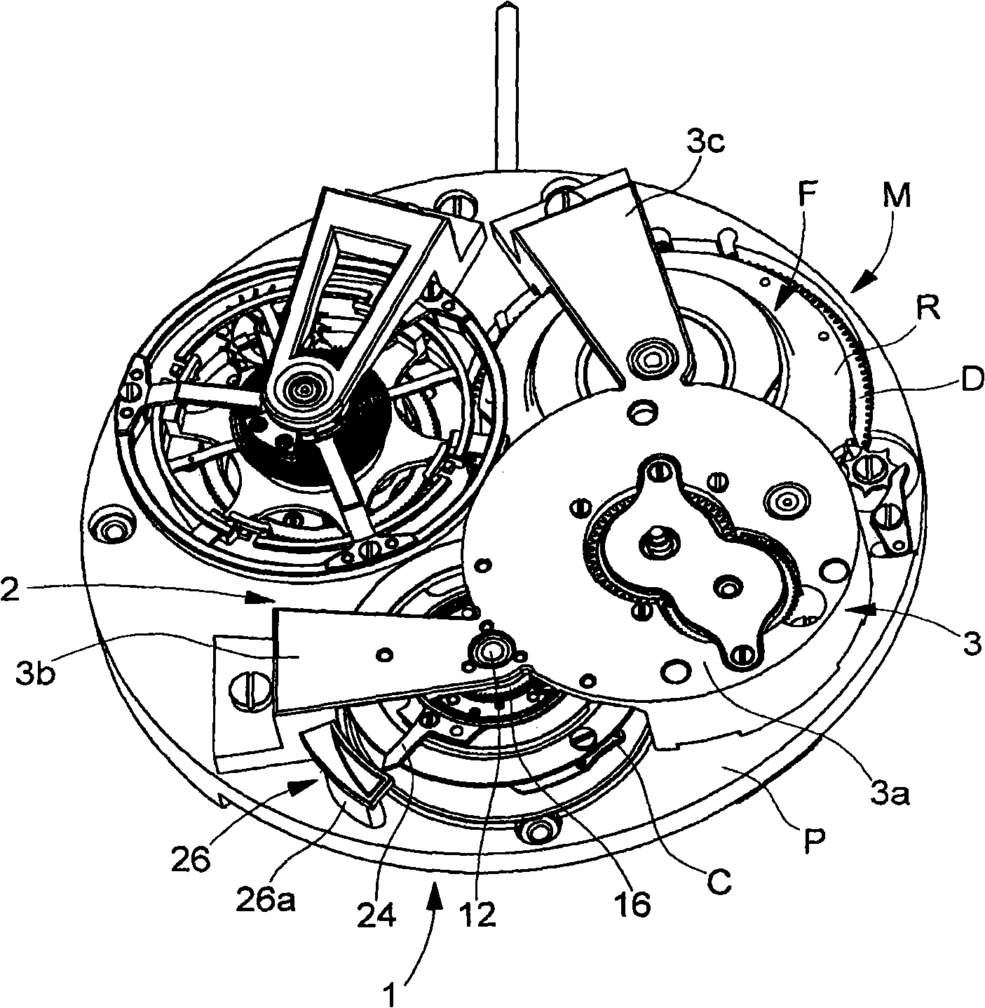
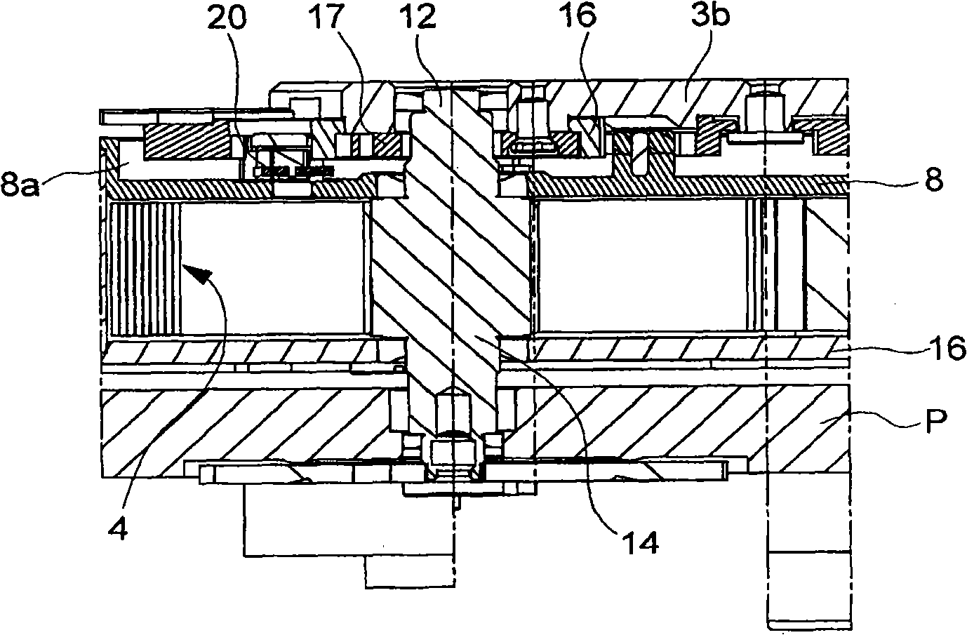
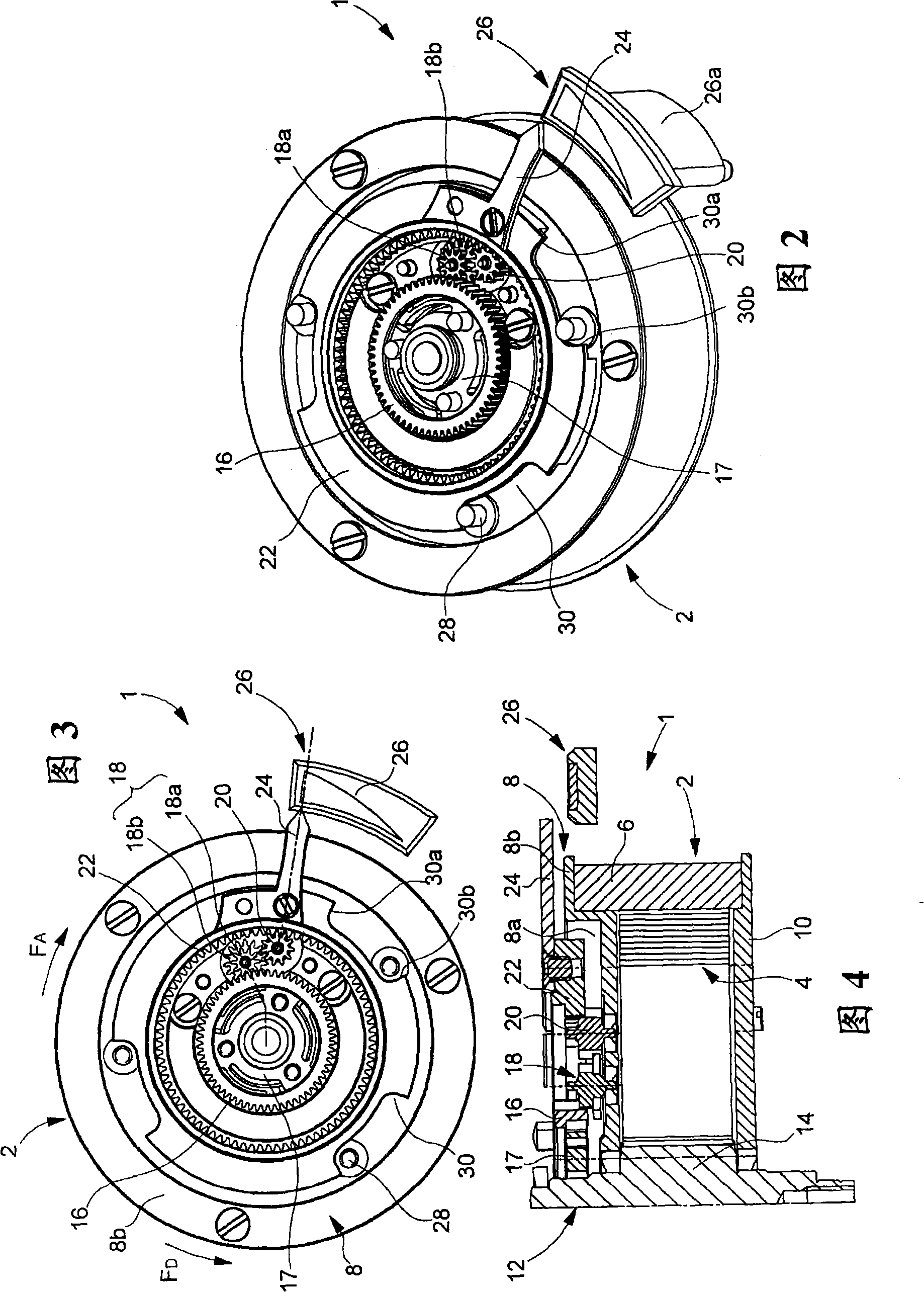
[0018] Figures 1 to 5 The view in part shows a chronograph, for example of the watch type, equipped with a power reserve indicator device according to the invention, indicated generally by the general numeral 1 . The watch comprises a watch movement M comprising a base plate P on which is mounted a barrel 2 housing a mainspring 4 . Barrel 2 comprises, in conventional manner, a barrel drum 6 closed by a cover 8 and a back cover 10 . Barrel 2 is mounted freely rotatable on barrel arbor 12 and fixed to core 14 . Mainspring 4 is hooked by its inner end to core 14 and by its outer end to the inner wall of barrel drum 6 . The barrel 2 is mounted in a conventional manner between the base plate P of the movement and a bridge 3 comprising a central part 3a from which a bridge branch 3b and a bridge branch 3c extend.

[0019] In the example shown, the power reserve indicator device 1 is intended to be connected to a barrel associated with a meaner F, also mounted on the base plate P...


PUM


Abstract

The present invention concerns a timepiece including a movement fitted with a power reserve indicator device, said timepiece including a barrel closed by a cover, a mainspring housed in said barrel and respectively connected to a barrel arbour and means for winding said mainspring, said indicator device including a differential gear kinematically connected by a first input to the barrel arbour, by a second input to the barrel and by an output to a power reserve indicator member and wherein the differential gear frame is arranged coaxially to the barrel arbour, characterized in that the second differential gear input is secured to the barrel cover, in that the differential gear output is formed by an inner toothed crown, in that the inner toothed crown is kinematically connected to the first input by at least first and second planetary wheel sets meshed with each other and in that the at least two planetary wheel sets are carried by the cover.

Description

technical field [0001] The invention relates to a chronograph comprising a power reserve indicator device, ie a device for indicating to the wearer the degree of winding of the barrel spring of a mechanical chronograph. Background technique [0002] The chronograph comprising the means for providing such a power reserve indication is designed to take into account the rotation of the ratchet during the winding of the barrel spring and the rotation of the barrel when the barrel spring is released. For this purpose, most of these known devices employ differential gears. A device of this type is disclosed, for example, in European Patent No. 1074897, in which the two differential inputs are connected respectively to the ring gear of the barrel drum and the ring gear of the ratchet wheel, and the differential gear output is connected to the indicator member. [0003] In order to show the number of windings of the barrel spring (which usually amounts to about 10 turns for the bar...

Claims


Application Information

Patent Timeline
Patent Type & Authority Applications(China)
IPC IPC(8): G04B9/00G04B13/00F16H1/28
CPCG04B9/00
Inventor A·佐格
Owner MONTRES BREGUET
Why Eureka
Try Eureka