Wave-based power generation system

a power generation system and wave technology, applied in sea energy generation, electrical equipment, engine fuctions, etc., can solve the problems of large-scale frameworks, large-scale structures built or deployed on the ocean, and difficult and costly construction of structures

Inactive Publication Date: 2011-02-22
KING FAHD UNIVERSITY OF PETROLEUM AND MINERALS
View PDF19 Cites 9 Cited by
  • Summary
  • Abstract
  • Description
  • Claims
  • Application Information

AI Technical Summary

Problems solved by technology

However, such systems typically require the construction of large and complex structures near the ocean or on ocean-mounted platforms.
Not only are such structures difficult and costly to build, but their large-scale frameworks, built or deployed on the ocean, are vulnerable to storm damage and are costly to maintain.

Method used


Image

  • Wave-based power generation system
  • Wave-based power generation system
  • Wave-based power generation system

Examples


Embodiment Construction

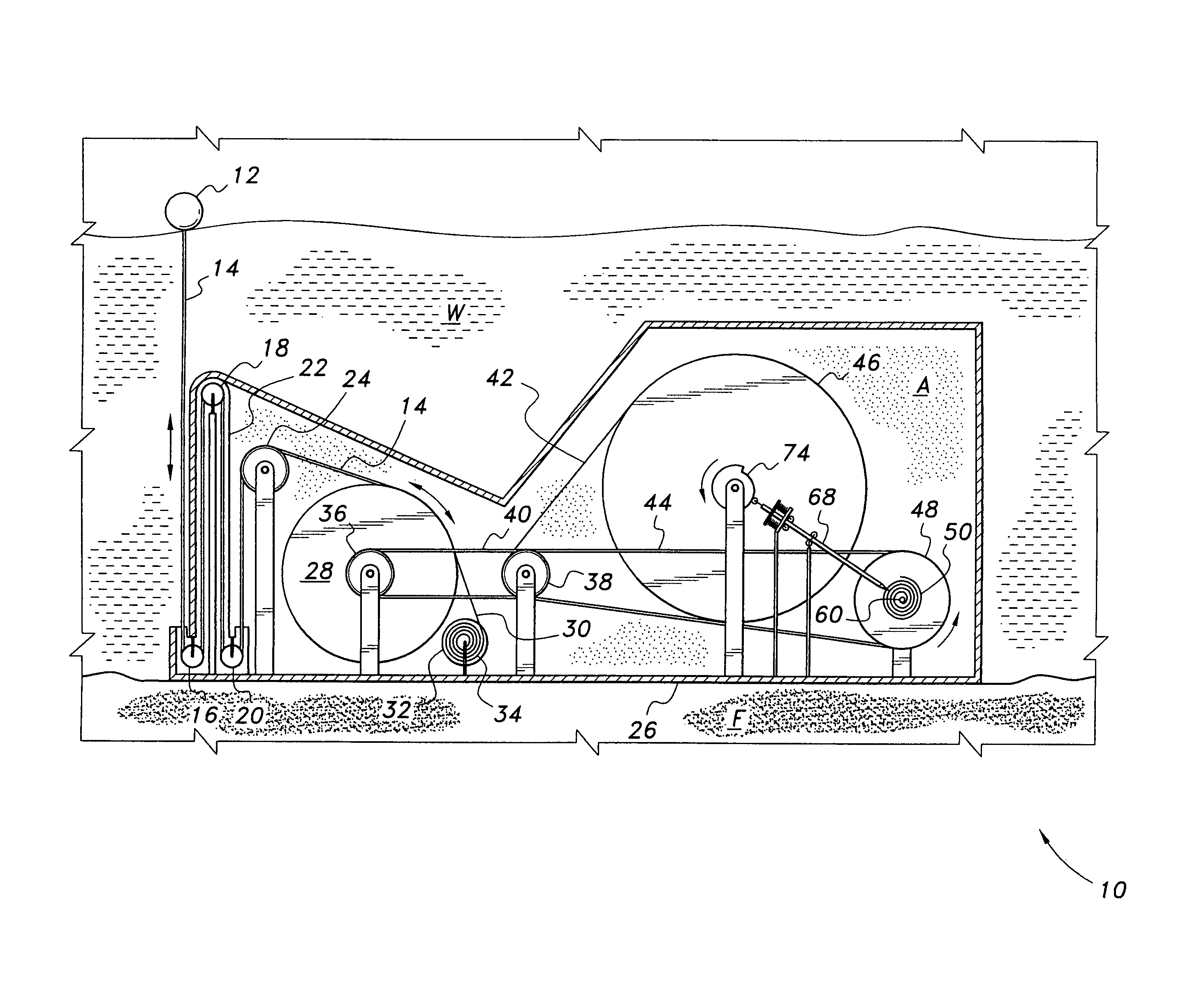
[0015]The present invention relates to a wave-based power generation system, designated generally as 10 in the drawings. Referring to FIG. 1, the system 10 includes a buoy or float 12 tethered by a cable 14 or other elongated flexible member resistant to corrosion, such as a string, a rope, a polyethylene cable, one or more strands of monofilament fishing line, a stainless steel, aluminum, or galvanized cable, etc. The cable 14 enters the housing 26 of an underwater power generation system through an inlet defined by an inverted U-tube 22 having upturned inlet and outlet ports, the housing defining a power generation chamber. The U-tube 22 provides for equilibration between the water pressure exerted by water W and air pressure exerted by air A within the housing in order to keep the machinery disposed within housing 26 dry.

[0016]Cable 14 is routed through an inlet pulley assembly 15, which includes pulleys 16, 18, and 20, disposed within the U-tube, and pulley 24, mounted on a bear...


PUM


Abstract

The wave-based power generation system has a buoy or float retained by a cable that enters an underwater power generating station. The cable enters the station housing through an inverted U-tube having upturned inlet and outlet ports, which prevent water from entering the housing. The buoy cable passes over an inlet pulley assembly disposed within the U-tube and has its free end secured to a take-up reel or sheave. A driver pulley is mounted on a shaft coaxial with the take-up reel shaft, and is constrained to unidirectional rotation. Rotation of the driver pulley is coupled to a mainspring pulley and a timing pulley through an idler pulley. A mainspring is compressed by rotation of the mainspring pulley until a cam wheel coaxial with the timing wheel releases a brake, causing the mainspring to expand and rotate a generator shaft to produce electricity.

Description

BACKGROUND OF THE INVENTION[0001]1. Field of the Invention[0002]The present invention relates to power generating systems, and particularly to a wave-based power generation system for generating electrical power from the motion of waves in a body of water.[0003]2. Description of the Related Art[0004]Due to the limitations of non-renewable energy sources, such as oil and coal, as well as the negative environmental effects of such energy sources, it is desirable to provide alternative energy conversion and transfer systems that are based on renewable sources of power with minimal effects on the environment. In recent years, systems for the conversion of the energy of ocean-based waves into electrical power have been of interest. However, such systems typically require the construction of large and complex structures near the ocean or on ocean-mounted platforms. Not only are such structures difficult and costly to build, but their large-scale frameworks, built or deployed on the ocean,...

Claims


Application Information

Patent Timeline
Patent Type & Authority Patents(United States)
IPC IPC(8): F03C1/00
CPCF03B13/1865F05B2240/97F05B2260/502F05B2260/504Y02E10/38Y02E10/30
Inventor AL-HUWAIDER, MUSTAFA ALI
Owner KING FAHD UNIVERSITY OF PETROLEUM AND MINERALS
Why Eureka
Try Eureka