
Multi-sensor event detection and tagging system

a multi-sensor, event technology, applied in the field of sensors, can solve the problems of increasing the requirements for power, bandwidth and memory, and the system cannot intelligently confirm events using multiple disparate types of sensors or social media or other non-sensor based information, and achieve the effect of saving labor

Active Publication Date: 2017-03-28
NEWLIGHT CAPITAL LLC
View PDF353 Cites 31 Cited by
  • Summary
  • Abstract
  • Description
  • Claims
  • Application Information

AI Technical Summary

Benefits of technology

[0030]By way of one or more embodiments, the microprocessor may determine the false positive event as detect a first value from the sensor values having a first threshold value and detect a second value from the sensor values having a second threshold value within a time window. In at least one embodiment, the microprocessor may then signify a prospective event, compare the prospective event to a characteristic signal associated with a typical event and eliminate any false positive events, signify a valid event if the prospective event is not a false positive event, and save the valid event in the sensor data memory including information within an event time window as the data.
[0124]One or more embodiments may provide the capability for users to manually add tags to events, and to filter or query events based on the automatic or manual tags. Embodiments of the system may generate a video highlight reel for a selected set of events matching a set of tags. One or more embodiments may discard portions of video based on the event analysis and tagging; for example, analysis may indicate a time interval with significant event activity, and video outside this time interval may be discarded, e.g., to save tremendous amounts of memory, and / or not transferred to another computer to save significant time in uploading the relevant events without the non-event data for example.

Problems solved by technology

Existing motion capture systems process and potentially store enormous amounts of data with respect to the actual events of interest.
These systems do not intelligently confirm events using multiple disparate types of sensors or social media or other non-sensor based information, including postings to determine whether an event has actually occurred, or what type of equipment or what type of activity has occurred.
Hence, capturing, transferring and storing non-event related data increases requirements for power, bandwidth and memory.
These systems are unable to monitor rotational accelerations or velocities and are therefore unable to detect certain types of events that may produce concussions.
In addition, many of these types of systems do not produce event related, connectionless messages for low power and longevity considerations.
Hence, these systems are limited in their use based on their lack of robust characteristics.
Thus, it is difficult and time consuming and requires manual labor to find, trim and designate particular motion related events for use in virtual reality for example.
Hence, current systems do not easily enable a particular user to play against a previously stored motion event of the same user or other user along with a historical player for example.
Furthermore, known systems do not take into account cumulative impacts, and for example with respect to data mined information related to concussions, to determine if a series of impacts may lead to impaired brain function over time.
This technique has various limitations including inaccurate and inconsistent subjective analysis based on video for example.
Known implementations utilize a stationary multi-camera system that is not portable and thus cannot be utilized outside of the environment where the system is installed, for example during an athletic event such as a golf tournament, football game or to monitor a child or elderly person.
These fixed installations are extremely expensive as well.
In addition, existing solutions do not contemplate mobile use, analysis and messaging and / or comparison to or use of previously stored motion capture data from the user or other users or data mining of large data sets of motion capture data, for example to obtain or create motion capture data associated with a group of users, for example professional golfers, tennis players, baseball players or players of any other sport to provide events associated with a “professional level” average or exceptional virtual reality opponent.
To summarize, motion capture data is generally used for immediate monitoring or sports performance feedback and generally has had limited and / or primitive use in other fields.
There are no known systems that allow for motion capture elements such as wireless sensors to seamlessly integrate or otherwise couple with a user or shoes, gloves, shirts, pants, belts, or other equipment, such as a baseball bat, tennis racquet, golf club, mouth piece for a boxer, football or soccer player, or protective mouthpiece utilized in any other contact sport for local analysis or later analysis in such a small format that the user is not aware that the sensors are located in or on these items.
In addition, for sports that utilize a piece of equipment and a ball, there are no known portable systems that allow the user to obtain immediate visual feedback regarding ball flight distance, swing speed, swing efficiency of the piece of equipment or how centered an impact of the ball is, i.e., where on the piece of equipment the collision of the ball has taken place.
These systems do not allow for user's to play games with the motion capture data acquired from other users, or historical players, or from their own previous performances.
Known systems do not allow for data mining motion capture data from a large number of swings to suggest or allow the searching for better or optimal equipment to match a user's motion capture data and do not enable original equipment manufacturers (OEMs) to make business decisions, e.g., improve their products, compare their products to other manufacturers, up-sell products or contact users that may purchase different or more profitable products.
In addition, there are no known systems that utilize motion capture data mining for equipment fitting and subsequent point-of-sale decision making for instantaneous purchasing of equipment that fits an athlete.
Furthermore, no known systems allow for custom order fulfillment such as assemble-to-order (ATO) for custom order fulfillment of sporting equipment, for example equipment that is built to customer specifications based on motion capture data mining, and shipped to the customer to complete the point of sales process, for example during play or virtual reality play.
In addition, there are no known systems that use a mobile device and RFID tags for passive compliance and monitoring applications.
There are no known systems that enable data mining for a large number of users related to their motion or motion of associated equipment to find patterns in the data that allows for business strategies to be determined based on heretofore undiscovered patterns related to motion.
There are no known systems that enable obtain payment from OEMs, medical professionals, gaming companies or other end users to allow data mining of motion data.
There are no known systems that create synchronized event videos containing both video capture and motion sensor data for events, store these synchronized event videos in a database, and use database analysis to generate models, metrics, reports, alerts, and graphics from the database.
In addition, the references do not contemplate a multi-sensor environment where other sensors may not observe or otherwise detect an event, while the sensor data is still valuable for obtaining metrics, and hence the references do not teach saving event data on other sensors after one sensor has identified an event.
There are no known systems that analyze data from motion sensors, video, radar, or other sensors to automatically select one or more tags for an event based on the data.

Method used


Image

  • Multi-sensor event detection and tagging system
  • Multi-sensor event detection and tagging system
  • Multi-sensor event detection and tagging system

Examples


Embodiment Construction

[0178]A multi-sensor event detection and tagging system will now be described. In the following exemplary description numerous specific details are set forth in order to provide a more thorough understanding of the ideas described throughout this specification. It will be apparent, however, to an artisan of ordinary skill that embodiments of ideas described herein may be practiced without incorporating all aspects of the specific details described herein. In other instances, specific aspects well known to those of ordinary skill in the art have not been described in detail so as not to obscure the disclosure. Readers should note that although examples of the innovative concepts are set forth throughout this disclosure, the claims, and the full scope of any equivalents, are what define the invention.

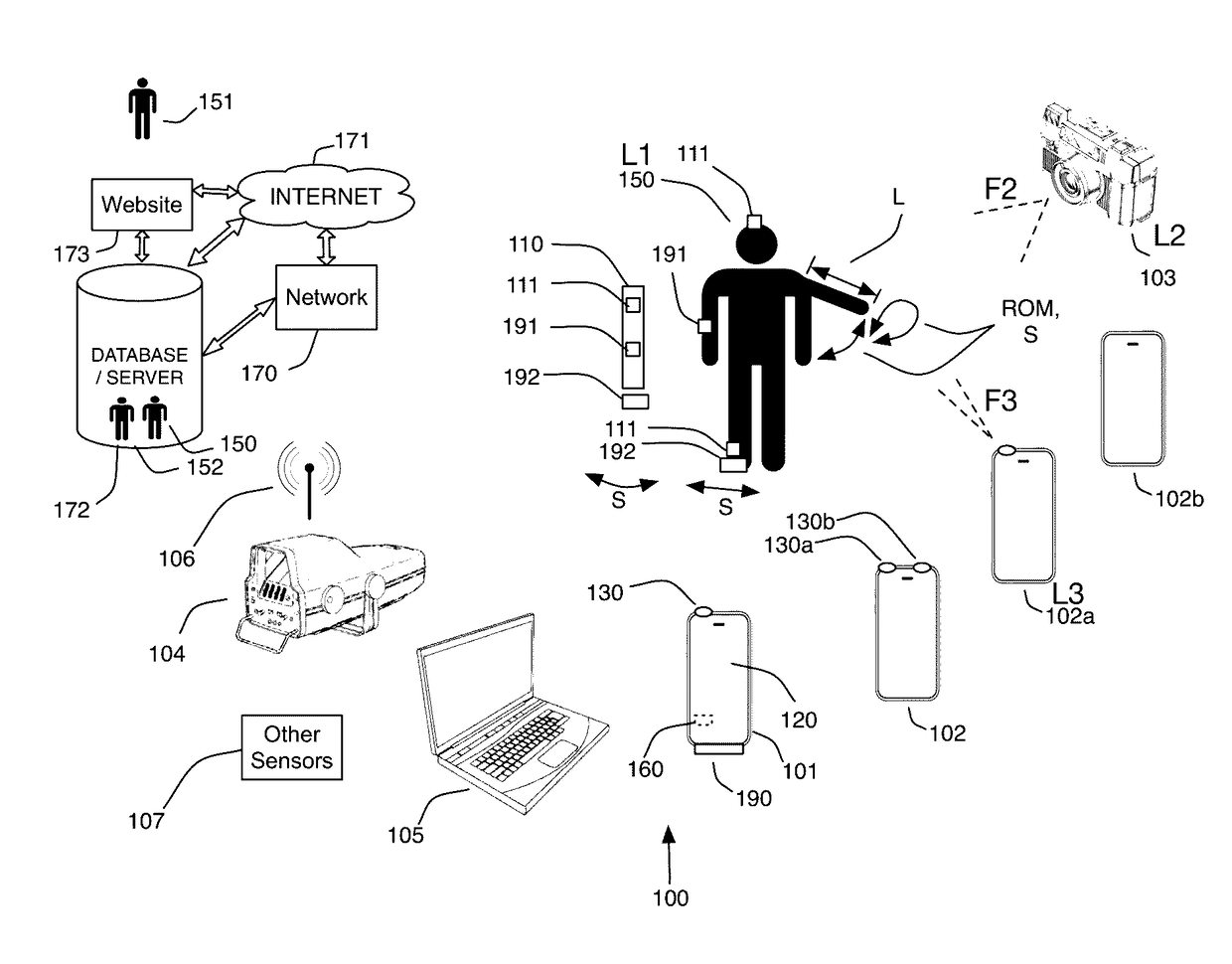
[0179]FIG. 1 illustrates an embodiment of the multi-sensor event detection and tagging system 100. At least one embodiments enables intelligent analysis of event data from a variety of se...


PUM

PropertyMeasurementUnit
time synchronizationaaaaaaaaaa
temperatureaaaaaaaaaa
altitudeaaaaaaaaaa

Abstract

A sensor event detection and tagging system that analyzes data from multiple sensors to detect an event and to automatically select or generate tags for the event. Sensors may include for example a motion capture sensor and one or more additional sensors that measure values such as temperature, humidity, wind or elevation. Tags and event detection may be performed by a microprocessor associated with or integrated with the sensors, or by a computer that receives data from the microprocessor. Tags may represent for example activity types, players, performance levels, or scoring results. The system may analyze social media postings to confirm or augment event tags. Users may filter and analyze saved events based on the assigned tags. The system may create highlight and fail reels filtered by metrics and by tags.

Description

[0001]This application is a continuation in part of U.S. Utility patent application Ser. No. 14 / 801,428 filed 16 Jul. 2015, which is a continuation in part of U.S. Utility patent application Ser. No. 14 / 549,422 filed 20 Nov. 2014, which is a continuation in part of U.S. Utility patent application Ser. No. 14 / 257,959 filed 21 Apr. 2014, which is a continuation-in-part of U.S. Utility patent application Ser. No. 13 / 914,525, filed 10 Jun. 2013, now U.S. Pat. No. 8,702,516, which is a continuation in part of U.S. Utility patent application Ser. No. 13 / 679,879 filed 16 Nov. 2012, which is a continuation-in-part of U.S. Utility patent application Ser. No. 13 / 298,158 filed 16 Nov. 2011, which is a continuation-in-part of U.S. Utility patent application Ser. No. 13 / 267,784 filed 6 Oct. 2011, which is a continuation-in-part of U.S. Utility patent application Ser. No. 13 / 219,525 filed 26 Aug. 2011, which is a continuation-in-part of U.S. Utility patent application Ser. No. 13 / 191,309 filed 26...

Claims


Application Information

Patent Timeline
Patent Type & Authority Patents(United States)
IPC IPC(8): A63B24/00A63B71/06G01P13/00G06T7/20G06K9/00G11B27/031G11B20/10A63F13/212A63F13/217A63F13/213A63F13/211H04N7/18H04N5/765H04N5/247G08B21/04
CPCG11B27/031A63B24/0062A63B71/06A63F13/211A63F13/212A63F13/213A63F13/217G01P13/00G06K9/00342G06K9/00711G06T7/20G08B21/043G11B20/10527H04N5/247H04N5/765H04N7/188A63F2300/105A63F2300/69G06K2009/00738G06T2207/30221G08B21/0492G11B2020/10592H04N5/77H04N5/91G08B25/016G06V40/23G06V20/42G06V20/44H04N23/80A63F13/00G06V20/40H04N23/90A63B24/0003A63B2024/0071A63B2220/34A63B2220/44A63B2220/803A63B2220/806A63B2225/20A63B2230/06G06T2207/10016G11B27/34
Inventor BOSE, BHASKARBENTLEY, MICHAELKAPS, RYAN
Owner NEWLIGHT CAPITAL LLC
Learn More