Implantation of flexible implant

a flexible implant and valve technology, applied in the field of valve repair, can solve the problems of reducing cardiac output, increasing total stroke volume, and ultimate weakening of the left ventricl

Active Publication Date: 2017-04-04
VALTECH CARDIO LTD
View PDF731 Cites 35 Cited by
  • Summary
  • Abstract
  • Description
  • Claims
  • Application Information

AI Technical Summary

Problems solved by technology

Mitral regurgitation of blood from the left ventricle into the left atrium results in increased total stroke volume and decreased cardiac output, and ultimate weakening of the left ventricle secondary to a volume overload and a pressure overload of the left atrium.

Method used


Image

  • Implantation of flexible implant
  • Implantation of flexible implant
  • Implantation of flexible implant

Examples


Embodiment Construction

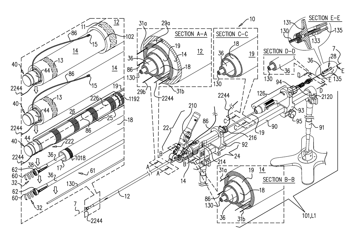
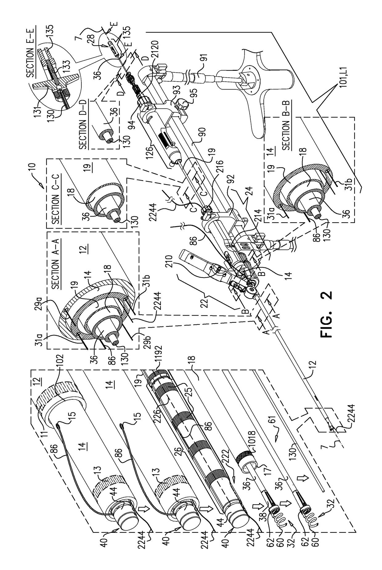
[0077]Reference is now made to FIGS. 1-2, which are schematic illustrations of a multi-component tubular system 10 providing one or more rotationally-controlled steering catheters configured for delivering an implant to a heart of a patient, in accordance with some applications of the present invention.

[0078]FIG. 1 shows a distal portion of an implant comprises an annuloplasty ring structure 222 (e.g., an annuloplasty band) comprising a flexible sleeve 26 (shown in the exploded view of FIG. 2). Sleeve 26 typically comprises a braided fabric mesh, e.g., comprising DACRON™. Sleeve 26 is typically configured to be placed only partially around a cardiac valve annulus (i.e., to assume a C-shape), and, once anchored in place, to be contracted so as to circumferentially tighten the valve annulus. Alternatively, the ring structure is configured to be placed entirely around the valve annulus.

[0079]Sleeve 26 has an elongated lateral tubular side wall 253 and at least one end wall 251 (e.g., a...


PUM


Abstract

A method is provided, including introducing into a heart atrium, an annuloplasty structure having a sleeve with an elongated tubular side wall and at least one distal end wall having a surface substantially transverse to a lateral surface of the tubular side wall. A first tissue anchor is deployed through the surface of the end wall of the sleeve and into a first portion of annulus tissue. A second tissue anchor is deployed through a portion of the tubular side wall and into a second portion of annulus tissue, such that the first tissue anchor and the second tissue anchor are both deployed consecutively, to extend in a substantially same direction and into a common, substantially planar surface of a valve annulus, the common, substantially planar surface including the first and second portions of the annulus tissue. Other applications are also described.

Description

FIELD OF THE INVENTION[0001]The present invention relates in general to valve repair, and more specifically to repair of an atrioventricular valve of a patient.BACKGROUND OF THE INVENTION[0002]Ischemic heart disease causes mitral regurgitation by the combination of ischemic dysfunction of the papillary muscles, and the dilatation of the left ventricle that is present in ischemic heart disease, with the subsequent displacement of the papillary muscles and the dilatation of the mitral valve annulus.[0003]Dilation of the annulus of the mitral valve prevents the valve leaflets from fully coapting when the valve is closed. Mitral regurgitation of blood from the left ventricle into the left atrium results in increased total stroke volume and decreased cardiac output, and ultimate weakening of the left ventricle secondary to a volume overload and a pressure overload of the left atrium.SUMMARY OF THE INVENTION[0004]In some embodiments of the present invention, an adjustable annuloplasty str...

Claims


Application Information

Patent Timeline
Patent Type & Authority Patents(United States)
IPC IPC(8): A61F2/24A61B90/30A61B17/068A61B17/064
CPCA61F2/2445A61B90/30A61F2/2466A61B17/068A61B2017/0649A61B2090/306A61B2090/309A61F2220/0008A61F2220/0016A61B17/064
Inventor ZIPORY, YUVALHAMMER, TAL
Owner VALTECH CARDIO LTD
Why Eureka
Try Eureka