Modular mount rack frame

a module and rack technology, applied in the direction of dismountable cabinets, movable shelf cabinets, electrical apparatus construction details, etc., can solve the problems of inflexibility for adjusting the horizontal dimension of the mount rack frame in the prior art storage structure, high cost and cumbersome cabinets for computer related devices,

Inactive Publication Date: 2017-04-04
YOUSIF GORGIUS L
View PDF4 Cites 1 Cited by
  • Summary
  • Abstract
  • Description
  • Claims
  • Application Information

AI Technical Summary

Benefits of technology

[0011]For example, a standard industry measurement of 3 U is equivalent to: (i) 57 inches in horizontal length of an attached device (or the modular rigid support structure), and (ii) 1.75×3 inches in height of the attached device (or vertical height interval along each rigid vertical component). Devices attach within each rigid support structure by sets of vertically and linearly aligned apertures and screws along the rigid vertical components. There are two sets of vertically and linearly aligned apertures along each rigid vertical component. As a result, the user can either attach the device more anterior or posterior along a modular rigid support structure.
[0012]In addition, each rigid vertical component end comprises apertures into which screws reversibly insert to attach a rack base. Each rack base comprises legs with locks, and coasters or wheels. These coasters or wheels provide mobility to the mount rack frame or single modular rigid support structure.
[0014]To increase the storage capacity of the new mount rack frame, one modular rigid support structure is stacked and aligned vertically upon the other. Since each modular rigid support structure is identical in structure and function to the other, all rigid support structures function either as the bottom or upper (stacked) modular unit. Connecting plates, as well as additional screws, along the corresponding rigid horizontal components reversibly attach an upper aligned rigid support structure upon the lower modular rigid support structure.
[0015]Accordingly, it is a purpose of the present invention to provide an economical manner in which to store computer-related devices without the use of shelves.
[0016]It is also a goal of the present invention to provide an economical manner in which to store any device which can be mounted to a mount frame rack with brackets.

Problems solved by technology

The prior art discloses cabinets for storage of computer related device which are expensive and cumbersome.
They also require humidity and temperature controls because of their non-ventilated interior environment.
Prior art storage structures also lack flexibility for adjusting the horizontal dimension of the mount rack frame whenever devices deviate from standard horizontal dimensions.
Furthermore, because these prior art storage structures are not modular, they cannot stack vertically upon each other in an interchangeable manner.

Method used


Image

  • Modular mount rack frame
  • Modular mount rack frame
  • Modular mount rack frame

Examples


Embodiment Construction

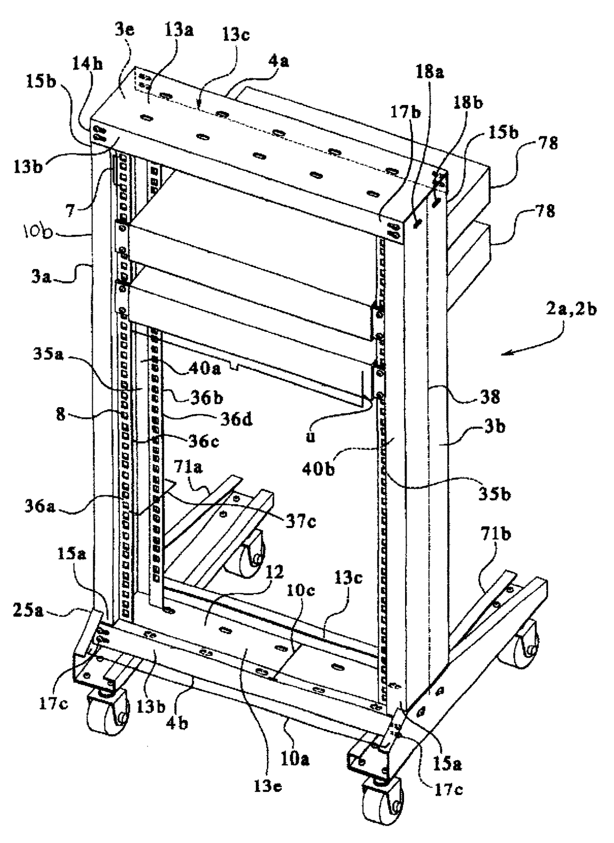
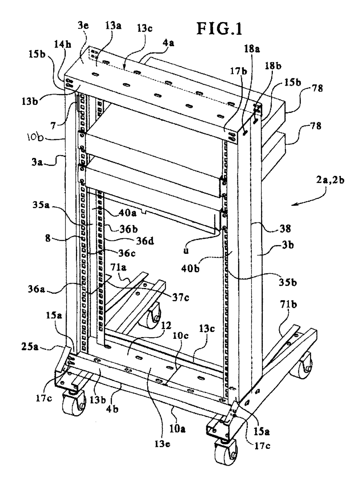
[0028]Referring to FIG. 1, the preferred embodiment of the mount rack frame 1 comprises a first modular rigid support structure 2a. In the FIG. 4 embodiment, there is an additional attached second modular rigid support structure 2b. Each first and second rigid support structure 2a, 2b, as well as other modular rigid support structures (generically designated modular rigid support structures 2), may differ in horizontal length, height and depth. However, each modular rigid support structure 2a, 2b is identical in function and structure to the other.

[0029]Each first or second modular rigid support structure 2a, 2b can support itself and one additional vertically stacked additional rigid support structure 2a, 2b whenever entire mount rack frame 1 rests upon a flat horizontal surface such as a floor. The discussion below addresses a first modular rigid support structure 2a. However the description of structure, technical details and function also apply to modular second rigid support st...


PUM

PropertyMeasurementUnit
longitudinal lengthaaaaaaaaaa
lengthaaaaaaaaaa
lengthaaaaaaaaaa

Abstract

A modular mount rack frame for storing mounted devices is described herein. A first embodiment of a mount rack frame includes a modular rigid support structure with linearly aligned apertures into which screws can reversibly insert to support a mounted device. In a second embodiment, first and second support structures are stacked and aligned vertically, and they mechanically attach to each other. In this second embodiment, either the first support structure or the second support structure can support the other while contacting a flat horizontal surface. Both first and second embodiments can attach to a rack base for mobility across the flat horizontal surface. Each rigid support structure is also laterally adjustable in horizontal length.

Description

[0001]This application is a continuation of U.S. patent application Ser. No. 13 / 068,471 filed May 12, 2011, and which is a continuation of U.S. patent application Ser. No. 11 / 236,495 filed Feb. 28, 2006 and its specification and drawings are incorporated herein in their entirety.BACKGROUND OF THE INVENTION[0002]This invention relates to a mount rack frame for storing computer related devices such as servers, hubs, switches and routers. More particularly this invention relates to a mount rack frame with congruently aligned apertures for connecting plates, horizontal length adjustment, and vertically attaching two individual modular rigid support structures. Connecting brackets simultaneously attach to the devices and the mount rack frame, thereby effectively stacking them within the frame without shelves.[0003]The prior art discloses cabinets for storage of computer related device which are expensive and cumbersome. They also require humidity and temperature controls because of their...

Claims


Application Information

Patent Timeline
Patent Type & Authority Patents(United States)
IPC IPC(8): H05K7/18A47B47/00A47B45/00
CPCH05K7/18A47B45/00A47B47/0091H05K7/1488A47B47/00A47B57/36H05K7/186
Inventor YOUSIF, GORGIUS L.
Owner YOUSIF GORGIUS L
Why Eureka
Try Eureka