Retractable drive system for watercraft

a technology of drive system and watercraft, which is applied in the direction of canoe/kayak, special-purpose vessels, vessel construction, etc., can solve the problems of propulsion device, and achieve the effect of improving personal watercra

Active Publication Date: 2017-04-18
JOHNSON OUTDOORS
View PDF22 Cites 15 Cited by
  • Summary
  • Abstract
  • Description
  • Claims
  • Application Information

AI Technical Summary

Problems solved by technology

Unfortunately, if the propulsion device contacts with the bottom of the body of water when approaching shore or when operating in shallow water, the propulsion device may become damaged or hung up on the bottom of the body of water inhibiting motion of the watercraft.

Method used


Image

  • Retractable drive system for watercraft
  • Retractable drive system for watercraft
  • Retractable drive system for watercraft

Examples


Embodiment Construction

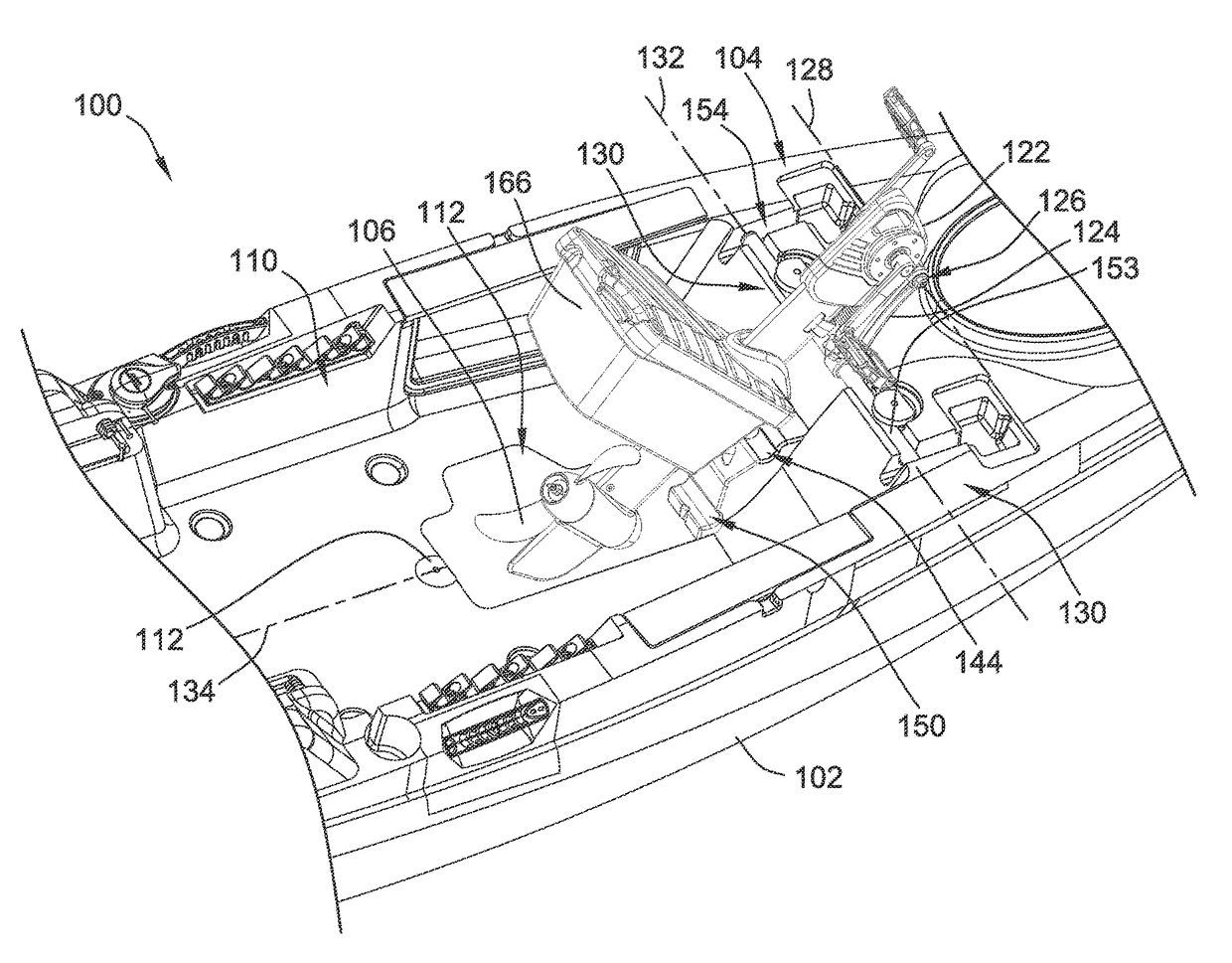
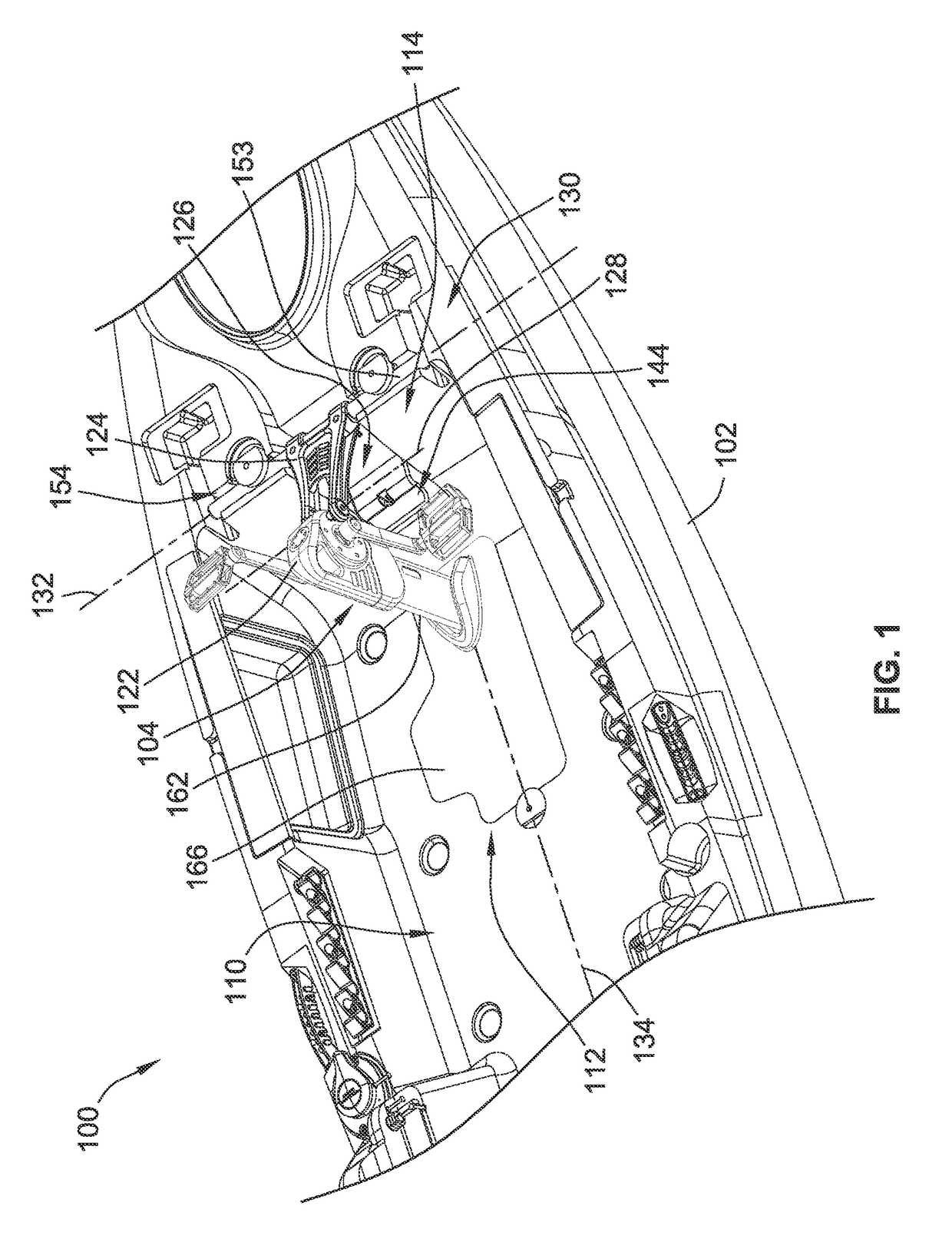
[0040]FIG. 1 illustrates an embodiment of a watercraft 100 according to the invention. The watercraft 100 is illustrated in the form of a kayak but could take other forms of watercraft such as canoes.

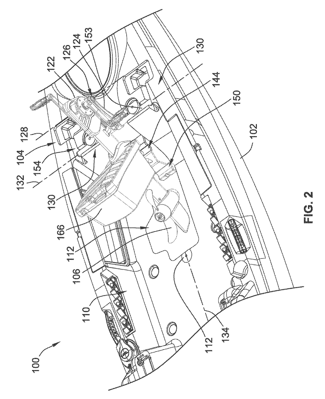
[0041]The watercraft 100 includes a hull 102 and a drive system 104 for converting an input from a user into a motive force for propelling the watercraft 100. In the illustrated embodiment, the drive system 104 is a pedal drive system that converts a pedaling motion from the user into motive force. With additional reference to FIG. 2, the drive system 104 uses the rotary motion from pedaling to rotationally drive a propeller 106. Other drive systems are contemplated. For instance, a pumping style drive system could be used where the user pushes back and forth on pedals rather than rotates pedals like in the illustrated embodiment to provide motive force. Further, rather than have a rotary driven propeller, reciprocating blades could be used to create the motive force for propelling the ...


PUM


Abstract

A drive system pivot assembly for a personal user powered watercraft is provided. The drive system pivot assembly pivots a drive system between a deployed position and a parked position. The drive system pivot assembly includes a catch arrangement for securing the drive system pivot assembly in the parked position.

Description

FIELD OF THE INVENTION[0001]This invention generally relates to drive systems for watercraft.BACKGROUND OF THE INVENTION[0002]It is desirable to have propulsion devices for self-propelling personal watercraft such as kayaks other than use of the typical paddle. One particular method of propelling personal watercraft is to use pedal systems that convert force produced by a user's legs into a propulsion force to propel the watercraft.[0003]For these propulsion devices to work efficiently, they must extend below the bottom of the personal watercraft such that an output of the propulsion device extends into the water.[0004]Unfortunately, if the propulsion device contacts with the bottom of the body of water when approaching shore or when operating in shallow water, the propulsion device may become damaged or hung up on the bottom of the body of water inhibiting motion of the watercraft.BRIEF SUMMARY OF THE INVENTION[0005]Embodiments of the invention relate to improvements in personal wa...

Claims


Application Information

Patent Timeline
Patent Type & Authority Patents(United States)
IPC IPC(8): B63H5/20B63H16/20B63B35/71
CPCB63H16/20B63B35/71B63H2016/202B63B34/26B63H16/18
Inventor KUEHMICHEL, BLAINE G.MCDONOUGH, ROBERT J.BERGMARK, GEOFFREY MICHAEL
Owner JOHNSON OUTDOORS
Why Eureka
Try Eureka