Photovoltaic panel racking system

Active Publication Date: 2017-04-18
POLAR RACKING
View PDF322 Cites 12 Cited by
  • Summary
  • Abstract
  • Description
  • Claims
  • Application Information

AI Technical Summary

Benefits of technology

This patent is about a system for mounting solar panels on a roof. The system uses special hardware to connect the panels to the roof, which adds stability and resistance to forces like wind and snow. The system is easy to install and only requires one tool. Overall, this invention makes it simpler and more secure to install solar on roofs.

Problems solved by technology

However, many of the known systems are complicated and installing such an array may take a considerable amount of time and may require a large number of tools.
Further, some known mounting or racking systems are susceptible to damage caused by wind, for example by having a panel lifted out of an array or by shearing forces applied to the array.

Method used


Image

  • Photovoltaic panel racking system
  • Photovoltaic panel racking system
  • Photovoltaic panel racking system

Examples


example 2

Array Support

[0079]This example describes more details of an illustrative embodiment of photovoltaic mounting system 400 described above in reference to FIG. 2; see FIGS. 19-21.

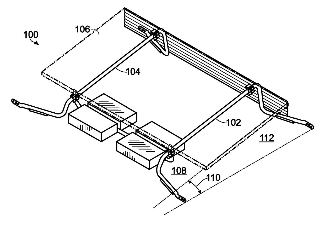
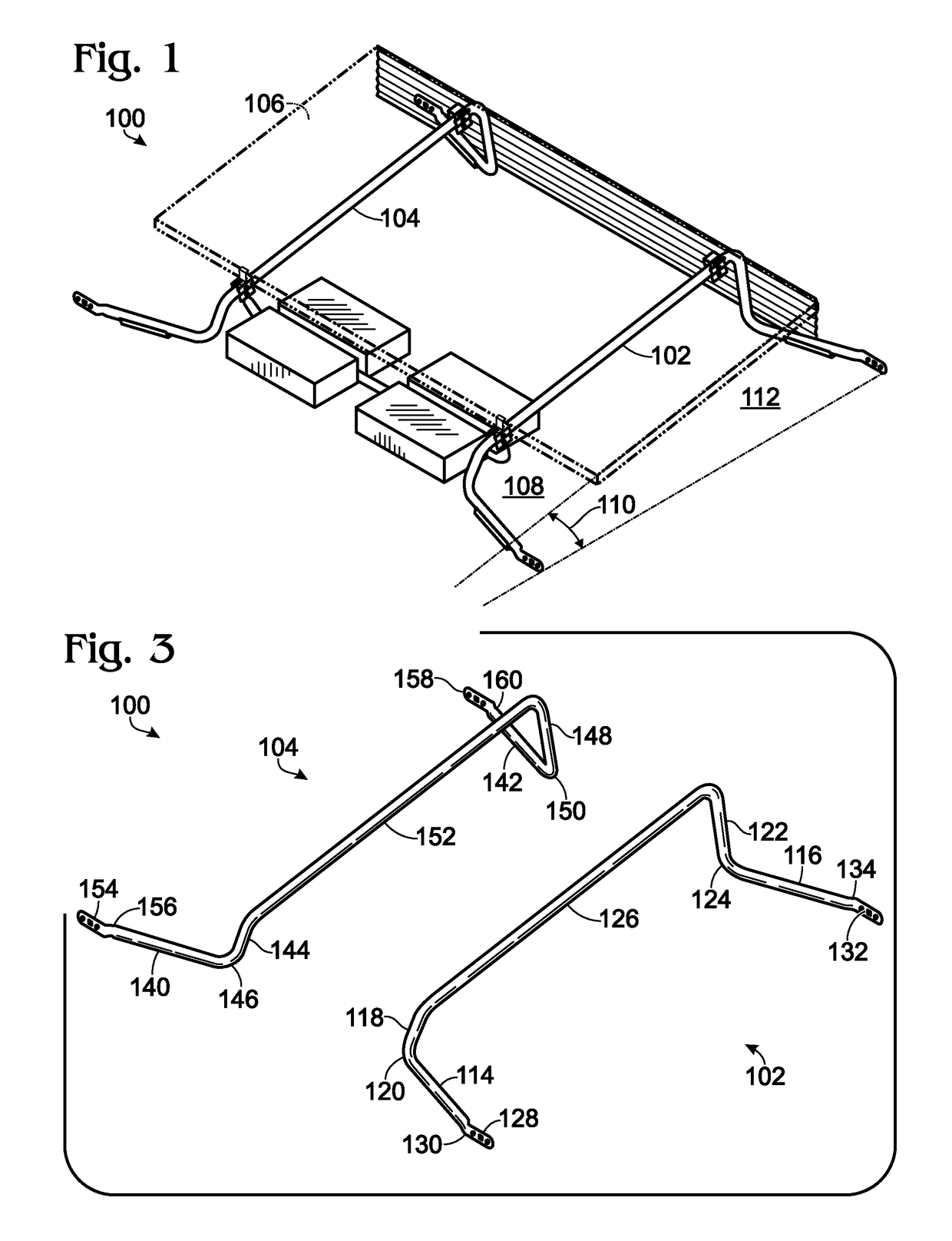
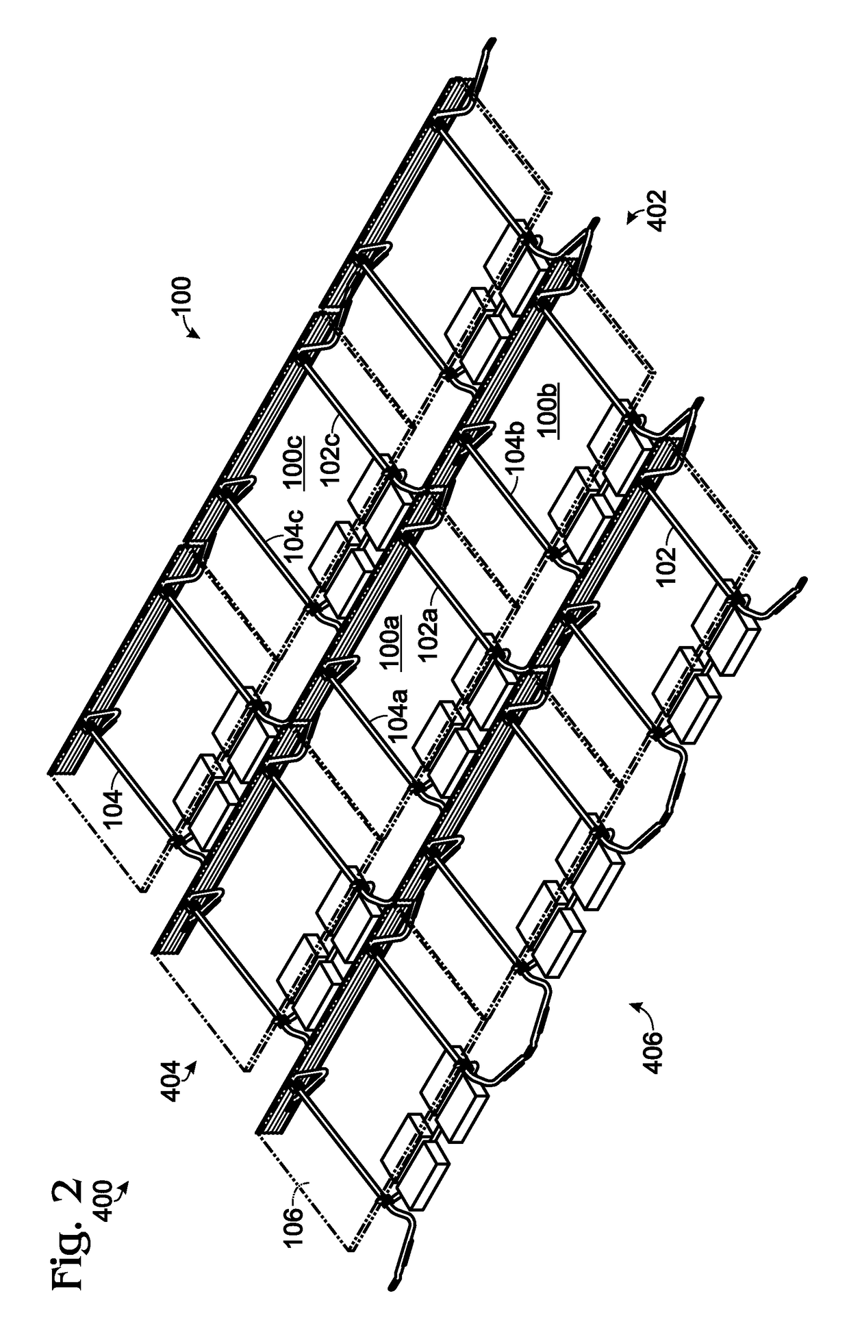
[0080]FIG. 19 is an isometric view of photovoltaic module mounting system 400, showing first plurality generally indicated at 402 of right-hand support runners 102, a second plurality generally indicated at 404 of left-hand support runners 104, and a plurality of u-shaped cross members 266 arranged to form an interconnected network of support runners. FIG. 19 is a simplified version of FIG. 2 which included such optional elements as ballast pans, ballast stones, support runner pads, and wind deflectors. Cross members 266 may also be optional, though in some cases the cross member may facilitate appropriate spacing of the right and left-hand support runners.

[0081]FIG. 20 is a detailed view of various connections between support runners in photovoltaic module mounting system 400. Specifically, FIG. 20 shows an ...


PUM


Abstract

A photovoltaic module mounting system may include a right-hand support runner and a left-hand support runner. The support runners collectively define a rooftop contacting plane and a photovoltaic module support plane oriented at a predetermined angle relative to the rooftop contacting plane. The support runners may be interconnected with each other, and with additional support runners, to form an interconnected support structure that can be used to mount an array of photovoltaic modules upon a planar surface such as a building rooftop.

Description

FIELD[0001]This disclosure relates to solar panels. More specifically, the disclosed embodiments relate to systems and methods for supporting one or more solar panels on a surface.INTRODUCTION[0002]There are known systems for supporting a photovoltaic solar panel or an array of panels on a flat surface such as a roof. However, many of the known systems are complicated and installing such an array may take a considerable amount of time and may require a large number of tools. Further, some known mounting or racking systems are susceptible to damage caused by wind, for example by having a panel lifted out of an array or by shearing forces applied to the array.[0003]There is a need for solar panel support racking systems which are easy to install, are easily adaptable to different installation constraints, which are resistant to shifting in linear directions due to wind forces, and which easily accommodate the electrical connections inherent to such an array.SUMMARY[0004]In some embodi...

Claims


Application Information

Patent Timeline
IPC IPC(8): H02S20/24
CPCH02S20/24Y02B10/20Y02E10/47F24S25/632F24S25/16F24S25/13F24S2025/02F24S25/636Y02E10/50Y02B10/10F24S25/30H02S20/10H02S20/20H02S20/22H02S20/23
Inventor ATCHA, IMRANRAILEANU, DORIN LUCIANMARENTETTE, MATTHEW PAULYARUSEVYCH, VOLODYMYR
Owner POLAR RACKING
Why Eureka
Try Eureka