Acoustic material flow sensor

a technology of acoustic material flow and sensor, which is applied in the field of precision agriculture, can solve the problems that the sensors that have been used to sense the necessary conditions, such as the load on the machine and the cleanliness of the crop being harvested, are inadequate for the job, and achieve the effect of optimizing machine performan

Active Publication Date: 2017-04-25
INTELLIGENT AGRI SOLUTIONS LLC
View PDF172 Cites 39 Cited by
  • Summary
  • Abstract
  • Description
  • Claims
  • Application Information

AI Technical Summary

Problems solved by technology

Attempts have been made to automate combines already, but the sensors that have been used to sense the necessary conditions, such as load on the machine and the cleanliness of the crop being harvested, are inadequate for the job.

Method used


Image

  • Acoustic material flow sensor
  • Acoustic material flow sensor
  • Acoustic material flow sensor

Examples


Embodiment Construction

I. Introduction and Environment

[0049]As required, detailed aspects of the present invention are disclosed herein, however, it is to be understood that the disclosed aspects are merely exemplary of the invention, which may be embodied in various forms. Therefore, specific structural and functional details disclosed herein are not to be interpreted as limiting, but merely as a basis for the claims and as a representative basis for teaching one skilled in the art how to variously employ the present invention in virtually any appropriately detailed structure.

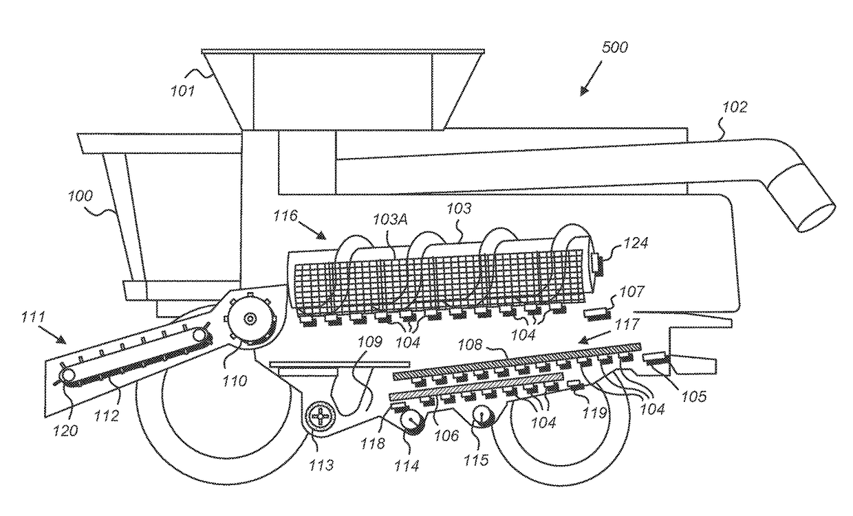
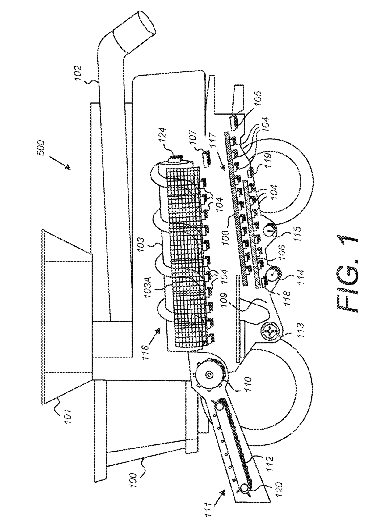
[0050]Certain terminology will be used in the following description for convenience in reference only and will not be limiting. For example, up, down, front, back, right and left refer to the invention as orientated in the view being referred to. The words, “inwardly” and “outwardly” refer to directions toward and away from, respectively, the geometric center of the aspect being described and designated parts thereof. Forwardly and ...


PUM

PropertyMeasurementUnit
massaaaaaaaaaa
densitiesaaaaaaaaaa
wavelengthsaaaaaaaaaa

Abstract

A material flow sensor for a harvesting machine comprising an acoustic chamber comprising an impact plate and a housing, microphone, a pneumatic impulse line connecting the housing and the microphone, and an electronics module, wherein the housing is shaped so as to direct sound waves created by crop matter striking the impact plate into the pneumatic impulse line, wherein the sound waves move through the pneumatic impulse line into the microphone, which detects the sound waves and converts them into an electrical signal that is a representation of the sound power derived from the sound waves, which in turn is a representation of the mass of the crop matter striking the material flow sensor.

Description

CROSS REFERENCE TO RELATED APPLICATIONS[0001]This patent application claims the benefit of U.S. Provisional Patent Application No. 62 / 049,616, filed Sep. 12, 2014 and entitled “METHOD AND SYSTEM FOR COMBINE AUTOMATION,” and is a continuation-in-part of and claims priority in U.S. patent application Ser. No. 13 / 843,029, filed Mar. 15, 2013 and entitled “VEHICLE CONTROL AND GATEWAY MODULE,” which is a continuation-in-part of and claims priority in U.S. patent application Ser. No. 13 / 046,549, filed Mar. 11, 2011, now U.S. Pat. No. 8,950,260, issued Feb. 10, 2015 and entitled “AIR SEEDER MONITORING AND EQUALIZATION SYSTEM USING ACOUSTIC SENSORS,” and is also a continuation-in-part of and claims priority in U.S. patent application Ser. No. 13 / 678,441, filed Nov. 15, 2012 and entitled “SYSTEM AND METHOD FOR DETERMINING MATERIAL YIELD AND / OR LOSS FROM A HARVESTING MACHINE USING ACOUSTIC SENSORS,” which claims the benefit of U.S. Provisional Patent Application No. 61 / 560,201, filed Nov. 15,...

Claims


Application Information

Patent Timeline
Patent Type & Authority Patents(United States)
IPC IPC(8): G01F1/66A01D41/127G01N33/00
CPCG01F1/662A01D41/1271A01D41/1272A01D41/1273G01F1/666G01N33/0098A01D41/1274A01D41/1276A01D41/1277
Inventor GELINSKE, JOSHUA N.BATCHELLER, BARRY D.NYSTUEN, PAUL A.REICH, ADAM A.THUROW, BRADLEY R.SCHLEUSNER, BRADLEY K.
Owner INTELLIGENT AGRI SOLUTIONS LLC
Why Eureka
Try Eureka