Method and apparatus for communicating in wind farms

a communication method and technology for wind farms, applied in electrical devices, digital transmission, data switching networks, etc., can solve the problems of subscriber units needing separate synchronization units or needing to be provided

Active Publication Date: 2017-04-25
SIEMENS GAMESA RENEWABLE ENERGY SERVICE GMBH
View PDF7 Cites 0 Cited by
  • Summary
  • Abstract
  • Description
  • Claims
  • Application Information

AI Technical Summary

Benefits of technology

[0020]The invention therefore provides for the individual installations on a wind farm to be permitted to send messages only at particular instants in a transmission interval. The effect achieved by this is that the number of messages sent in a particular time period is limited, which means that the number of messages received and intended to be processed on each installation in a time period is also limited. This allows overflow of the input buffer of the installations to be prevented. The transmission interval is repeated cyclically, so that the individual installations are permitted to send messages regularly at particular instants.
[0023]In the case of the method according to the invention, the synchronization is thus effected not on the basis of a special synchronization message—as is still the case in the prior art—but rather on the basis of the messages sent by the individual installations to all the other installations on the wind farm. Since an installation receives all the messages from the other installations on the wind farm, this one installation can independently determine the installation at the first position in the order. On the basis of a message from the installation at the first position in the order, the one installation can in turn ascertain the instant at which it is permitted to send a message. This affords the advantage that there is a need neither for special synchronization messages, which are fundamentally to the detriment of the useful data rate, nor for specially designed synchronization units. The fail-safety of the system is also very high, since the redundancy level for synchronization of the installations on the wind farm corresponds to the number of these installations in practice.
[0024]The assignment of instants for sending messages within a transmission interval, according to the invention, affords a good level of robustness even when individual installations do not send any messages in a transmission interval. The reason is that an installation that is subsequent in accordance with the position in the order sends its messages regardless of whether the installation that is preceding in accordance with the position in the order has sent messages.
[0027]It is preferred if after two transmission intervals in which messages from the installation at the first position in the order are absent, the installation at the next highest position in the order becomes the installation at the first position in the order. The reference that is used to synchronize the transmission intervals of the individual installations is altered by this measure if the installation at the inherently first position in the order sends no further messages or corresponding messages are at least absent, for example on account of a fault. The synchronization of the individual installations is restored within a short time, namely no later than after two transmission intervals, as a result. Should the installation at the originally first position in the order be reactivated and send messages again, for example because the fault has been corrected, this installation can be used as the installation at the first position in the order again. The individual installations are then synchronized using the messages from this installation again.
[0029]It is preferred if the gap between two adjacent instants in the transmission interval at which installations send messages is chosen such that overflow of the reception buffers for messages at the installations is avoided. It is thus possible to ensure that the number of messages sent to each installation does not exceed, in a particular time interval, the number of messages that can be processed at most by the individual installations within the time interval. Furthermore, a safety factor may be provided, so that, even in the event of a brief malfunction in an installation when the messages in its input buffer are processed, said input buffer does not overflow. Furthermore, provision may be made for particular installations, for example the farm master, to be permitted to send messages to all the, or individual, installations on the wind farm at each instant without there being the risk of overflow of an input buffer for one of or all the other installations. Even messages from installations that do not send messages in synchronized fashion should not regularly result in an overflow of the input buffers. To achieve this, the number of messages regularly sent in a time interval can be chosen to be lower than the maximum number possible. This results in an adequate buffer for additional messages.
[0033]It is preferred that between the instant at which the installation at the last position in the order in the transmission interval sends a message and the end of the transmission interval there is a time buffer provided, i.e. between said last instant and the start of the next transmission interval there is a certain period of time provided in which there is no provision for messages to be sent. The time buffer makes it possible to ensure that inaccuracies in the synchronization or small malfunctions in the installations do not result in messages from one transmission interval being sent in the next transmission interval.

Problems solved by technology

A disadvantage of this prior art is that separate synchronization units need to be provided or subscriber units need to be designed specifically for the operation of a synchronization unit.
Furthermore, this prior art requires an explicit synchronization message that cannot contain any useful data, or can contain useful data only to a reduced extent.

Method used


Image

  • Method and apparatus for communicating in wind farms
  • Method and apparatus for communicating in wind farms
  • Method and apparatus for communicating in wind farms

Examples


Embodiment Construction

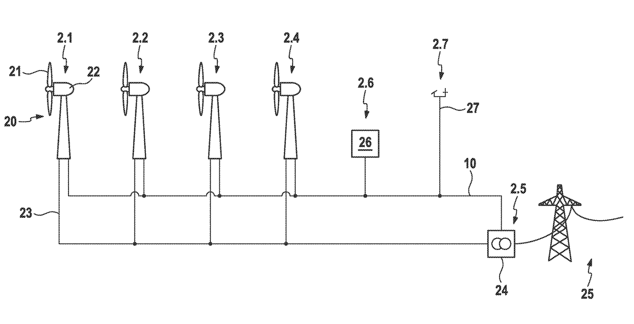
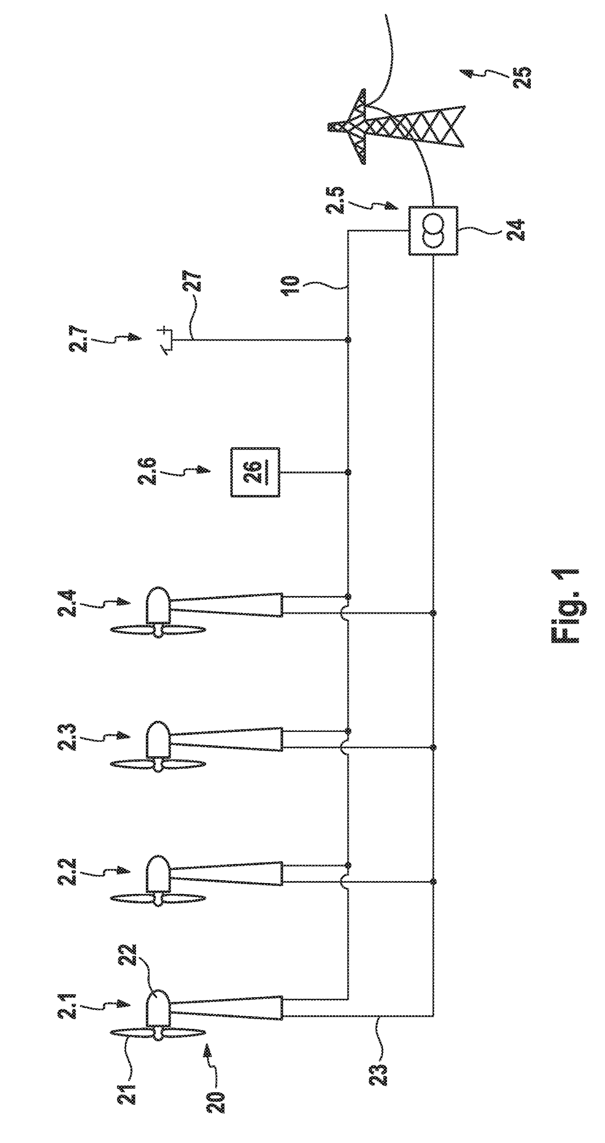
[0044]In all the exemplary embodiments, it is assumed for reasons of clarity that the order of the individual installations is formed from an installation number sorted in ascending order. The installation number is a sortable feature of every installation. The installation with the lowest installation number adopts the first position in the order, the installation with the next highest installation number adopts the second position, etc. Instead of the installation number, however, it is also possible to use any other arbitrary sortable feature. Equally, reverse sorting, i.e. sorting in descending order from the highest feature or the highest installation number, is also possible.

[0045]FIG. 1 shows a wind farm 1 having a multiplicity of installations 2. The installations 2 all have an installation number 1 to 7, which for reasons of clarity are shown as a suffix to the reference symbols.

[0046]The installations 2.1 to 2.4 are wind energy installations 20, in which a rotor having rot...


PUM


Abstract

In the method according to the invention for communicating between installations, which are organized in an order according to a sortable feature, for example installation numbers, in a wind farm, in which information transmitted by an installation in the form of a message is received by all other installations in the wind farm, a cyclically recurring, temporal transmission interval is set up. A point in time in the transmission interval at which the installation can transmit a message is assigned to each installation on the basis of the position thereof in the order, wherein points in time are organized from the start of the transmission interval, starting from the installation number at the first position in the order, in accordance with the position in the order. The start of the transmission interval is synchronized in all installations using a message from the installation at the first position in the order.

Description

REFERENCE TO RELATED APPLICATIONS[0001]This application is a national stage application under 35 USC 371 of International Application No. PCT / EP2013 / 056445, filed Mar. 26, 2013, which claims priority to German Application No. 10 2012 204 944.4, filed Mar. 28, 2012, the entire contents of which are incorporated herein by reference.FIELD OF THE INVENTION[0002]The invention relates to a method for communication between installations in a wind farm and to an installation that is suitable for carrying out the method according to the invention.BACKGROUND OF THE INVENTION[0003]Wind farms usually comprise multiple wind energy installations, with the power produced in the wind energy installations being fed into a public grid via a network that is internal to the wind farm. In order to check and possibly adjust the quality of the power fed into the grid by the wind farm, there is frequently also what is known as a farm master provided that can send control specifications to the individual wi...

Claims


Application Information

Patent Timeline
Patent Type & Authority Patents(United States)
IPC IPC(8): H04L12/417
CPCH04L12/417Y02E10/72
Inventor STILLE, LARS
Owner SIEMENS GAMESA RENEWABLE ENERGY SERVICE GMBH
Why Eureka
Try Eureka