Tray separator method and apparatus

a separator and trays technology, applied in the direction of transportation and packaging, de-stacking articles, etc., can solve the problems of up to 25% of the trays being damaged, the nested containers tend to be tightly compacted, and the person attempting to separate the trays is easy to damag

Active Publication Date: 2017-05-02
BARR JIMMY W
View PDF18 Cites 1 Cited by
  • Summary
  • Abstract
  • Description
  • Claims
  • Application Information

AI Technical Summary

Benefits of technology

[0003]It is an object of the present invention to provide a method and apparatus for separating container trays from a stack of such trays which minimizes or eliminates damage to the trays.
[0006]A plurality of separator fingers are positioned in alignment with opposing linear pathways formed between the lowermost tray in the stack and the tray adjacent thereto. A separator linear actuator cause the separator fingers to retract to a location out of contact with the stack during a non-separation mode of operation, and to cause the separator fingers to be substantially fully inserted into the linear pathways during a separation mode of operation. The separator fingers are configured to expand the distance between adjacent webs during insertion to cause the lowermost tray to detach from the tray adjacent thereto.

Problems solved by technology

During shipping the nested containers tend to become tightly compacted.
Since the containers have thin walls, it is easy for the person attempting to separate the trays to damage some of them.
Typically up to 25% of the trays are damaged during separation.
The damaged trays must be discarded, leading to a large amount of wastage.

Method used


Image

  • Tray separator method and apparatus
  • Tray separator method and apparatus
  • Tray separator method and apparatus

Examples


Embodiment Construction

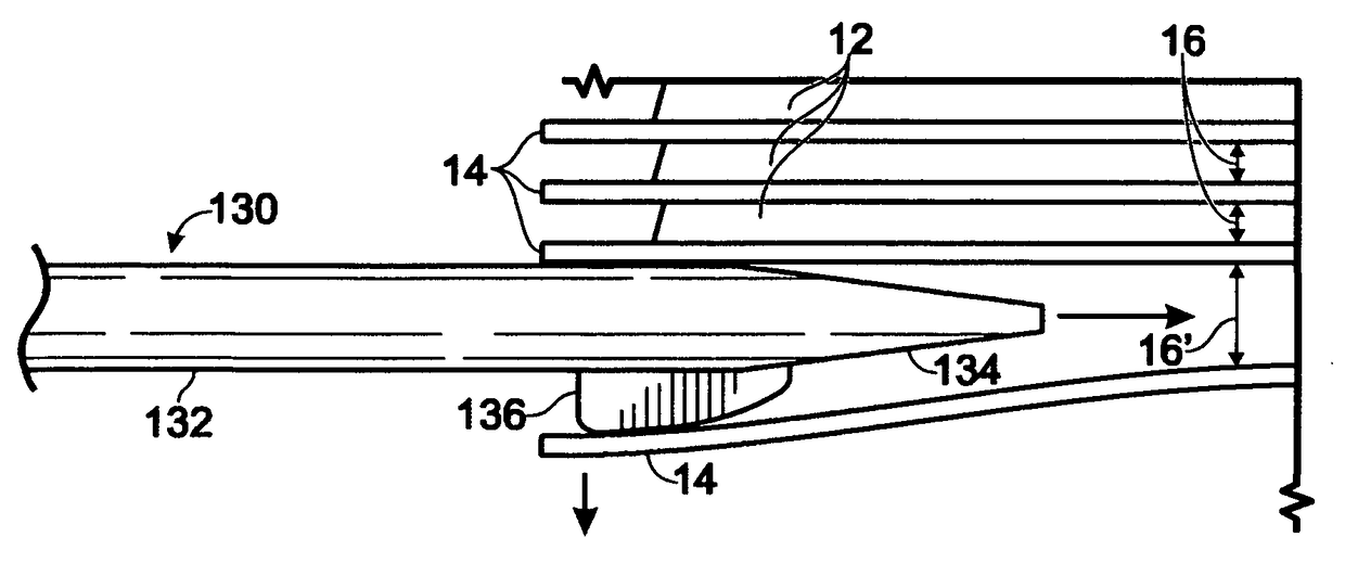
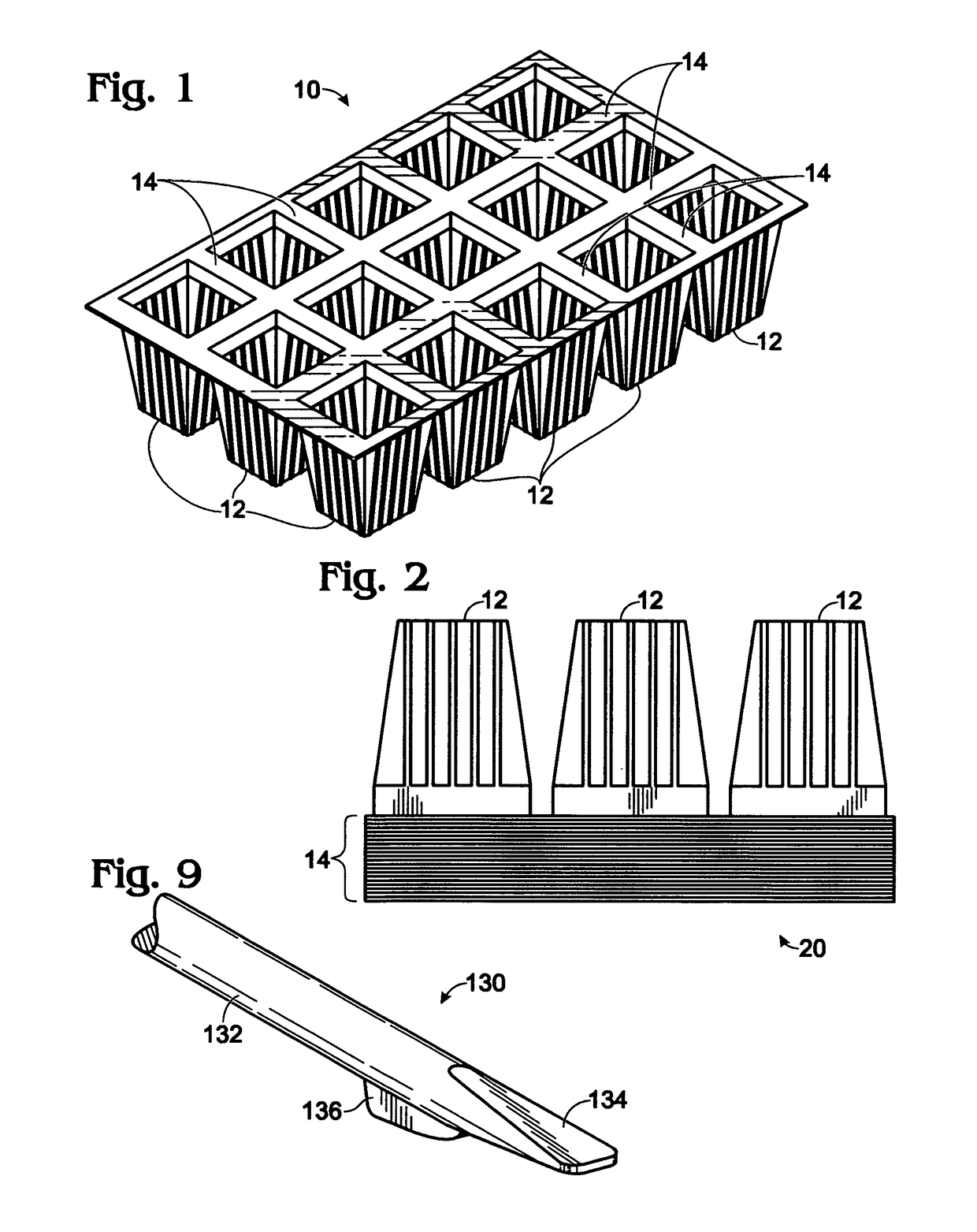
[0018]FIG. 1 shows a rectangular container tray 10 consisting of a plurality of interconnected containers 12 arranged in rows and columns. Tray 10 is formed by any suitable plastic forming process, such as injection molding. Each container 12 is connected to adjacent containers 12 at their upper edges by webs 14.

[0019]For purposes of illustration tray 10 is shown containing three rows of five containers, or five columns of three containers, for a total of fifteen containers per tray. However, the separator method and apparatus of the present invention may be used with container trays containing a different number of containers so long as they are arranged in rows and columns with space in between forming linear pathways.

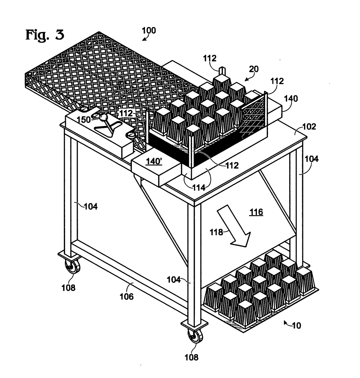
[0020]As seen in FIG. 2, a plurality of container trays 10 are nested together to form a stack 20 for shipment to a customer. For purposes of illustration, stack 20 is shown as containing twenty-one nested container trays 10. Although the containers 12 of one tray ar...


PUM


Abstract

A method and apparatus for separating a stack of trays, each tray being comprised of a plurality of spaced apart containers arranged in rows and columns and interconnected by webs located at their upper, open ends, the containers of each tray in the stack being nested within the containers of an adjacent tray, the space between the tops of adjacent containers in a row or column and the space between adjacent webs forming linear pathways through the stack. The apparatus includes a magazine for holding a stack of the trays. The magazine includes a plurality of first and second support fingers located at the first and second ends of the stack. First and second support linear actuators cause the support fingers to be extended to a stack support location during a non-separation mode of operation, and cause the support fingers to retract to a non-stack support location during the separation mode of operation. A plurality of separator fingers are positioned in alignment with opposing linear pathways formed between the lowermost tray in the stack and the tray adjacent thereto. A separator linear actuator cause the separator fingers to retract to a location out of contact with the stack during a non-separation mode of operation, and to cause the separator fingers to be substantially fully inserted into the linear pathways during a separation mode of operation. The separator fingers are configured to expand the distance between adjacent webs during insertion to cause the lowermost tray to detach from the tray adjacent thereto.

Description

BACKGROUND OF THE INVENTION[0001]The present invention relates to a method of separating nested trays of containers from a stack thereof, and an apparatus for carrying out the method.[0002]Plastic containers, such as those made by injection molding high density polyethylene, are widely used for a variety of purposes, such as for holding plant cuttings and seedlings, packing berries, etc. A typical such array of containers is shown in FIG. 1 and consists of a plurality of containers joined together at their upper edges to form a tray of containers. Such trays are stacked together with the exterior of the containers of an upper tray nesting inside the containers in the tray immediately below, as seen in FIG. 2. During shipping the nested containers tend to become tightly compacted. The nursery man or berry packer must separate or “de-nest” the individual trays for use, which currently is done manually. Since the containers have thin walls, it is easy for the person attempting to separ...

Claims


Application Information

Patent Timeline
Patent Type & Authority Patents(United States)
IPC IPC(8): B65G59/00B65G59/10
CPCB65G59/105
Inventor BARR, JIMMY W.
Owner BARR JIMMY W
Why Eureka
Try Eureka